Ultrasonic Fuel Sensor
Ultrasonic Fuel Sensor
In the landscape of industrial automation and fleet management, the accurate monitoring of fuel levels is critical for operational efficiency, cost control, and theft prevention. The ultrasonic fuel sensor has emerged as a leading non-invasive technology for measuring liquid levels in both stationary storage tanks and mobile vehicle tanks. Unlike traditional float-based sensors that are prone to mechanical wear and inaccuracies caused by fuel sloshing, ultrasonic technology offers a high-precision, solid-state solution that requires minimal maintenance.
This guide examines the engineering principles, selection criteria, and practical installation requirements for ultrasonic fuel sensors, providing a technical framework for engineers and procurement professionals to evaluate these instruments within their specific process environments.
Measurement Principle of Ultrasonic Fuel Sensors
Ultrasonic fuel sensors operate on the Time-of-Flight (ToF) principle. The device utilizes a piezoelectric transducer to emit high-frequency sound waves—typically in the range of 40 kHz to 200 kHz. These waves travel through a medium (either the air gap above the fuel or the fuel itself, depending on the mounting style) until they encounter a change in density at the liquid-gas interface.
Upon hitting the fuel surface, the ultrasonic pulse is reflected back to the transducer, which then acts as a receiver. The sensor’s internal processor measures the exact time interval between the emission of the pulse and the reception of the echo. The distance is calculated using the formula:
Distance = (Speed of Sound × Time) / 2
In a top-mounted configuration, the sensor measures the distance to the fuel surface (ullage). By knowing the total height of the tank, the system subtracts the measured distance from the total height to determine the fuel level. In bottom-mounted, non-invasive configurations, the sensor transmits the pulse through the tank wall and the liquid, reflecting off the fuel-air interface from below. This latter method is particularly popular for mobile assets because it does not require drilling into the fuel tank.
Signal Processing and Compensation
The speed of sound is not constant; it varies significantly with temperature and the density of the medium. For instance, the speed of sound in diesel vapor differs from that in gasoline vapor. Professional-grade ultrasonic fuel sensors incorporate integrated temperature sensors to apply real-time compensation algorithms, ensuring accuracy remains within ±0.5% to ±1% of the total range across varying environmental conditions.
Key Evaluation Criteria for Industrial Selection
When selecting an ultrasonic fuel sensor for a project, several technical specifications must be prioritized to ensure long-term reliability and data integrity.
1. Measurement Range and Blind Zone
Every ultrasonic sensor has a "blind zone" (also known as a dead zone) directly in front of the transducer face where it cannot accurately process returning echoes. For fuel tanks, this is typically between 50 mm and 200 mm. Selecting a sensor with a blind zone that matches the tank's geometry is essential to avoid data loss when the tank is at maximum capacity.
2. Output Interfaces and Integration
For B2B applications, the sensor must integrate seamlessly with existing Telematics units, PLCs, or SCADA systems. Common interfaces include:
* Analog Outputs: 0–5V or 4–20mA, ideal for simple integration with industrial controllers.
* Digital Interfaces: RS232 or RS485 (Modbus RTU), which allow for long-distance data transmission and the daisy-chaining of multiple sensors.
* Wireless Options: Integration with LoRaWAN or NB-IoT for remote stationary tanks.
3. Material Compatibility and IP Rating
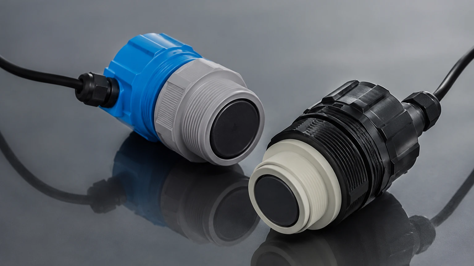
Fuel environments are chemically aggressive. Sensors must be constructed from materials like stainless steel or high-grade fluoropolymers (PTFE/PVDF). For mobile applications, an IP67 or IP68 rating is mandatory to protect the electronics against high-pressure washing, rain, and fuel splashes.
Comparison of Fuel Level Measurement Technologies
To assist in the selection process, the following table compares the ultrasonic fuel sensor against other common industrial level measurement technologies available on the Main Page.
| Feature | Ultrasonic (External) | Ultrasonic (Internal) | Capacitive | Hydrostatic | Radar (60GHz/80GHz) |
| :— | :— | :— | :— | :— | :— |
| Installation | Non-invasive (Bottom) | Top-mount (Drilled) | Top-mount (Drilled) | Submersible/Side | Top-mount (Non-contact) |
| Accuracy | ±1.0% | ±0.5% | ±1.0% | ±0.5% | ±0.1% |
| Maintenance | Very Low | Low | Medium (Cleaning) | Medium | Very Low |
| Fuel Compatibility | Diesel/Gasoline | Diesel/Gasoline | Non-conductive only | Most fuels | All liquids |
| Cost | Moderate | Moderate | Low to Moderate | Moderate | High |
| Best Use Case | Fleet Tracking | Stationary Tanks | Small Gen-sets | Deep Storage | Chemical/High Precision |
Installation Considerations and Best Practices
Proper installation is the most significant factor determining the success of an ultrasonic fuel sensor deployment. Failure to follow engineering guidelines often results in "ghost echoes" or signal loss.
Mounting Location
The sensor should be installed at the center of the tank's top (for internal) or bottom (for external) whenever possible. This minimizes the risk of the ultrasonic beam hitting the tank walls or internal baffles. If a tank has internal structural supports, the sensor must be positioned to provide a clear "line of sight" to the fuel surface.
Surface Preparation (External Sensors)
For bottom-mounted, non-invasive ultrasonic fuel sensors, the contact point on the exterior of the tank must be sanded to bare metal to remove paint, rust, or debris. A specialized acoustic coupling grease is applied between the transducer and the tank surface to eliminate air gaps, which would otherwise reflect the ultrasonic energy before it enters the tank.
Tank Geometry and Baffles
In mobile applications (trucks, heavy machinery), fuel tanks often contain baffles to prevent surging. The ultrasonic fuel sensor should be placed in a compartment that represents the average level. Advanced sensors include software filtering to average out the fluctuations caused by vehicle movement, providing a stable reading even while the asset is in motion.
Limitations and Operational Risks
While highly versatile, ultrasonic technology has specific limitations that engineers must account for during the design phase:
1. Foaming: High-speed filling of diesel can create foam on the liquid surface. Ultrasonic waves are absorbed by foam rather than reflected, which can cause the sensor to report a "tank empty" error or a loss of signal. In such cases, a stilling well or a transition to radar technology may be required.
2. Heavy Vapor/Pressure: In high-pressure tanks or tanks with extremely volatile fuels, the density of the vapor space can change rapidly, significantly affecting the speed of sound. If the sensor does not have sophisticated vapor compensation, the accuracy will degrade.
3. Tank Bottom Sludge: For external, bottom-mounted sensors, the accumulation of sediment or sludge at the bottom of the tank can attenuate the signal. Regular tank cleaning or periodic recalibration of the signal gain is necessary in older storage systems.
4. Internal Obstructions: Ladders, heating coils, or sensors mounted too close to the side wall will create false reflections. Most modern sensors allow for "false echo suppression," where the software is programmed to ignore reflections at specific distances.
Frequently Asked Questions (FAQs)
Q: Can an ultrasonic fuel sensor be used for gasoline?
A: Yes, but with caution. Gasoline is more volatile than diesel, leading to higher vapor concentrations. It is critical to use an intrinsically safe (ATEX/IECEx certified) sensor and ensure the device has adequate temperature and vapor compensation.
Q: What is the typical lifespan of these sensors?
A: Since there are no moving parts to wear out, a high-quality industrial ultrasonic fuel sensor can last 5 to 10 years, provided the housing materials are compatible with the fuel type and environmental conditions.
Q: Does the tank material affect the sensor?
A: For internal, top-mounted sensors, the tank material is irrelevant. For external, bottom-mounted sensors, the technology works best on metal tanks (steel or aluminum). It can work on plastic tanks, but the wall thickness and plastic density must be consistent to allow sound transmission.
Q: How is the sensor calibrated?
A: Calibration is usually performed by defining the "Full" and "Empty" points in the sensor's software. For complex tank shapes (e.g., cylindrical horizontal tanks), a multi-point calibration table (strapping table) is uploaded to the sensor or the tracking software to convert level (mm) into volume (liters).
Conclusion
The ultrasonic fuel sensor provides a robust, high-precision solution for modern fuel management challenges. By understanding the physics of sound propagation and adhering to strict installation protocols, industrial operators can achieve reliable data that drives better decision-making. For complex applications involving varied tank geometries or specialized fuel types, it is recommended to Review product options and application support to ensure the selected instrument meets the specific demands of the operational environment.