Electronic Water Level
Electronic Water Level
In modern industrial and municipal operations, the transition from manual or mechanical monitoring to electronic water level measurement has become a standard for efficiency and safety. Electronic systems provide real-time data, high precision, and the ability to integrate with SCADA (Supervisory Control and Data Acquisition) systems, which is essential for water treatment, chemical processing, and industrial automation. Understanding the underlying technologies and selection criteria is critical for engineers and facility managers tasked with maintaining reliable liquid level control.
Core Measurement Principles
Before selecting a specific instrument, it is necessary to understand the physical principles that drive electronic water level sensing. Each technology interacts with the medium and the environment differently.
1. Hydrostatic Pressure Measurement
Hydrostatic level transmitters operate on the principle that the pressure at a specific point in a static liquid is proportional to the height of the liquid column above it. The relationship is defined by the formula: $P = \rho \cdot g \cdot h$, where $P$ is pressure, $\rho$ is the density of the liquid, $g$ is the gravitational constant, and $h$ is the height of the liquid.
In practice, a submersible sensor or a flange-mounted pressure transmitter measures this force. For electronic water level monitoring in deep wells or reservoirs, submersible sensors are common. They feature a sensing diaphragm and a vented cable that allows the sensor to compensate for atmospheric pressure changes, ensuring that only the liquid column's weight is measured.
2. Ultrasonic (Non-Contact) Measurement
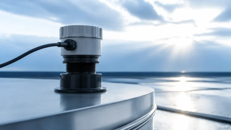
Ultrasonic sensors emit high-frequency sound pulses that travel through the air to the water surface and reflect back to the transducer. The device measures the "time-of-flight"—the duration between the emission of the pulse and the reception of the echo. Since the speed of sound in air is known (approximately 343 m/s at 20°C), the distance to the water surface can be calculated.
This method is ideal for corrosive liquids or wastewater because the sensor never touches the medium. However, it is sensitive to air temperature fluctuations, heavy foam, and steam, which can attenuate the sound signal.
3. Radar (Non-Contact) Measurement
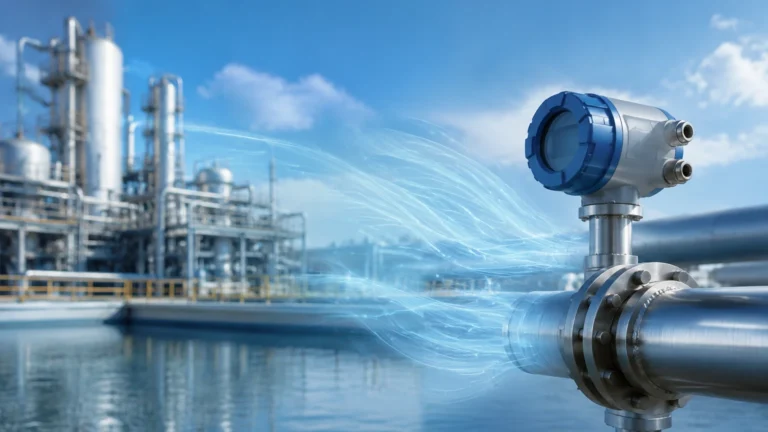
Radar level meters use high-frequency electromagnetic waves (typically in the 26GHz or 80GHz range) instead of sound. Like ultrasonic sensors, they use the time-of-flight principle or Frequency Modulated Continuous Wave (FMCW) technology.
Radar is often considered the gold standard for electronic water level monitoring in challenging environments. Because electromagnetic waves do not require a medium to travel, they are unaffected by vacuum, high pressure, or temperature variations. 80GHz radar, in particular, offers a very narrow beam angle, allowing it to measure accurately in narrow tanks or near internal obstructions like agitators.
4. Capacitance and Conductivity
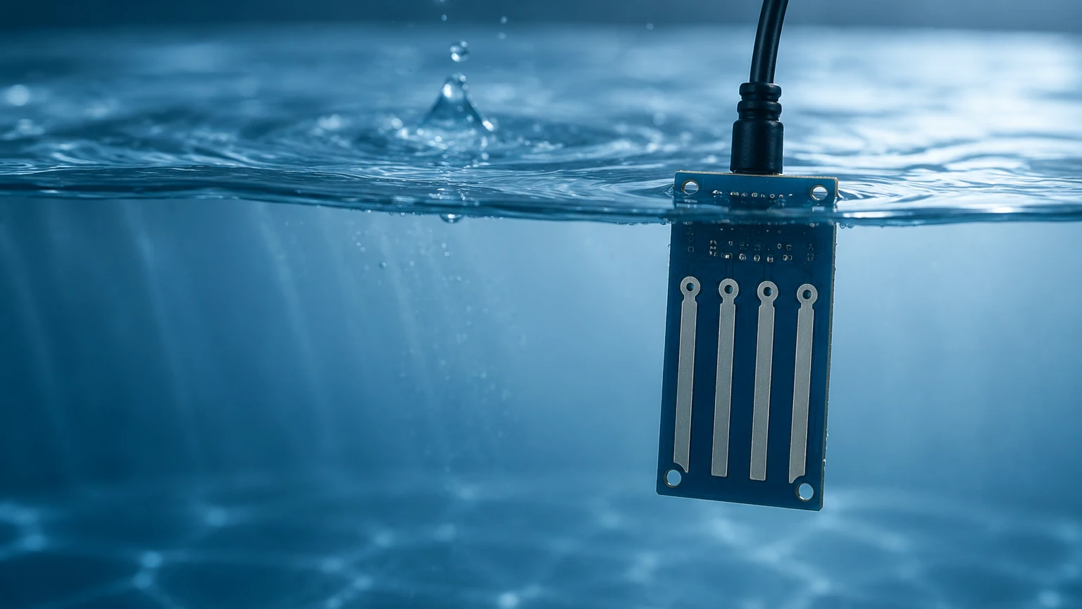
Conductivity-based electronic water level systems use probes to detect the presence of water at specific points. When water touches the probe, an electrical circuit is completed. This is primarily used for point-level detection (high or low alarms). Capacitive sensors, on the other hand, measure the change in capacitance between two electrodes (or one electrode and the tank wall) as the water level rises, providing continuous measurement.
Practical Selection Criteria for Industrial Applications
Choosing the right electronic water level solution requires a balance between environmental conditions, required accuracy, and budget. For a comprehensive overview of available technologies, engineers often consult the Main Page of specialized manufacturers to compare technical specifications.
| Technology | Accuracy | Range | Best For | Limitations |
| :— | :— | :— | :— | :— |
| Hydrostatic | ±0.1% to ±0.5% | Up to 200m (656 ft) | Deep wells, vented tanks | Affected by density changes |
| Ultrasonic | ±0.25% | 0.3m – 15m (1 – 49 ft) | Wastewater, open channels | Sensitive to foam and steam |
| Radar (80GHz) | ±1mm (0.04 in) | Up to 120m (393 ft) | Chemical tanks, high precision | Higher initial cost |
| Magnetic Gauge | ±5mm (0.2 in) | Up to 6m (20 ft) | High-pressure boilers | Requires bypass pipe installation |
Installation Considerations and Best Practices
Correct installation is as vital as selecting the right technology. Even the most advanced electronic water level sensor will fail if environmental factors are ignored.
Dead Zones and Blanking Distances
Non-contact sensors (ultrasonic and radar) have a "dead zone" immediately below the transducer where measurements cannot be taken. For example, an ultrasonic sensor might have a 0.3m (1 ft) dead zone. If the tank overfills into this zone, the sensor may report an error or a false "empty" reading. Always install the sensor high enough to ensure the maximum water level remains below the dead zone.
Stilling Wells and Bypass Pipes
In applications with high turbulence or surface agitation (such as mixing tanks), electronic water level sensors may struggle to provide a stable reading. Installing the sensor inside a stilling well—a vertical pipe that dampens surface waves—can significantly improve accuracy. For magnetic level gauges, a bypass pipe mounted to the side of the tank is standard practice.
Environmental Protection
For outdoor installations, such as reservoir monitoring or flood control, sensors must be rated for IP68 (ingress protection) to withstand submersion and heavy rain. Furthermore, electronic components should be shielded from direct sunlight using sunshades to prevent overheating and UV degradation of the housing. In regions prone to lightning, surge protection modules are mandatory to protect the 4-20mA or RS485 communication loops.
Common Risks and Mitigation Strategies
While electronic water level systems are highly reliable, certain risks can compromise data integrity:
* Density Fluctuations: Hydrostatic sensors assume a constant liquid density. If the water temperature changes significantly or if chemicals are added that alter the density, the level reading will drift. In these cases, radar is a safer alternative.
* Signal Interference: For radar and ultrasonic sensors, internal tank structures like ladders, pipes, or heating coils can create "false echoes." Advanced electronic level meters include "false wave suppression" software, allowing the user to map out these obstructions during commissioning.
* Condensation and Buildup: In humid environments, condensation can form on the face of an ultrasonic transducer, blocking the signal. Radar sensors with PTFE (Teflon) lenses are better suited for these conditions as they are more resistant to moisture accumulation.
Integration and Data Output
Modern electronic water level instruments typically offer several output options for integration into B2B industrial ecosystems:
1. 4-20mA Analog: The industry standard for long-distance signal transmission with high noise immunity.
2. HART Protocol: Allows digital communication over the same 4-20mA wires, providing diagnostic data and remote configuration.
3. RS485 Modbus: Ideal for connecting multiple sensors to a single PLC (Programmable Logic Controller) or RTU (Remote Terminal Unit) in a daisy-chain configuration.
4. Wireless (LoRaWAN/NB-IoT): Increasingly used for remote water level monitoring in smart city and agricultural applications where wiring is cost-prohibitive.
Frequently Asked Questions (FAQ)
Q: Can electronic water level sensors be used in potable water?
A: Yes, but the materials in contact with the water (such as the stainless steel of a hydrostatic sensor or the flange of a radar unit) must be food-grade or certified by organizations like the NSF.
Q: How often do these sensors need calibration?
A: Most high-quality electronic sensors are factory-calibrated and have very low drift. However, in critical applications, an annual verification against a manual tape measure or a reference gauge is recommended.
Q: What is the difference between a level transmitter and a level switch?
A: A level transmitter provides continuous measurement (e.g., 0% to 100% full), while a level switch only detects if the water has reached a specific point (e.g., a high-level alarm).
Q: Is radar better than ultrasonic for wastewater?
A: Generally, yes. Wastewater often produces foam and vapors that can interfere with ultrasonic sound waves. Radar electromagnetic waves penetrate these obstacles more effectively.
Conclusion
Implementing an effective electronic water level system requires a thorough analysis of the application's physical constraints and the specific properties of the water being measured. By understanding the principles of hydrostatic, ultrasonic, and radar technologies, engineers can select a solution that minimizes maintenance while maximizing accuracy. For those seeking specific product hardware or customized OEM solutions, visiting the Main Page of a dedicated manufacturer like Welk provides access to technical datasheets and application support necessary for successful project execution.