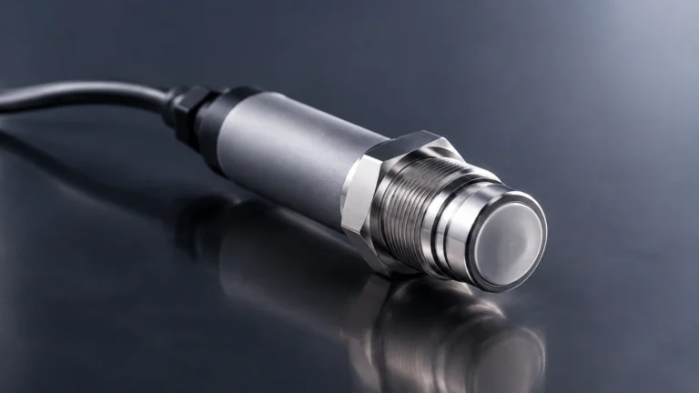
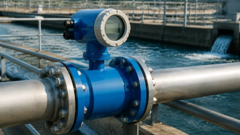
In Line Flow Switch
In Line Flow Switch
In industrial process control, the ability to detect the presence or absence of fluid movement is critical for equipment protection and process automation. An in line flow switch serves as a fundamental safety and control component, designed to trigger an electrical signal when a specific flow rate is reached or when flow stops entirely. Unlike continuous flow meters that provide a constant stream of data, a flow switch operates on a set-point basis, acting as a binary "watchdog" for pumps, cooling systems, and chemical dosing lines.
Integrating an in line flow switch into a piping system allows operators to prevent catastrophic failures, such as pump dry-running, heater burnout, or the loss of essential cooling media. This article examines the underlying measurement principles, selection criteria, and engineering best practices for deploying these instruments in professional B2B environments.
Measurement Principles of In Line Flow Switches
Before selecting a specific model, it is essential to understand the physical principles that govern how these devices detect fluid movement. The choice of technology significantly impacts the instrument's longevity, pressure drop, and suitability for different fluid types.
1. Thermal Dispersion Principle
Thermal dispersion flow switches are solid-state devices with no moving parts. The sensing head contains two temperature sensors: one is heated to a constant temperature above the fluid, and the other acts as a reference, measuring the actual fluid temperature.
When the fluid is stationary, the temperature difference between the two sensors is at its maximum. As the fluid begins to flow, it carries heat away from the heated sensor. This cooling effect is proportional to the flow velocity. The electronics detect this change in temperature differential and trigger the switch once the flow crosses the pre-defined threshold. Because there are no mechanical components to wear out, thermal switches are highly reliable for both liquids and gases, particularly in applications involving high-purity water or corrosive chemicals.
2. Paddle (Vane) Principle
This is one of the most common mechanical principles. A paddle or vane is suspended in the fluid stream. As the fluid flows, it exerts dynamic pressure on the paddle, pushing it forward. This movement is transmitted through a mechanical linkage or a magnetic coupling to an internal microswitch.
Paddle switches are robust and cost-effective, making them ideal for large-diameter pipes (DN50 and above). However, they are sensitive to turbulence and may suffer from mechanical fatigue over millions of cycles. They are best suited for clean, low-viscosity liquids like water or light oils.
3. Piston (Shuttle) Principle
In a piston-style in line flow switch, a calibrated piston is housed within the instrument body. The flow of the fluid forces the piston to move against a precision spring. The piston contains a permanent magnet that actuates a reed switch located outside the fluid path.
This design is highly accurate for low flow rates and provides excellent repeatability. Because the spring return is predictable, these switches can be mounted in various orientations. They are commonly used in lubrication systems and hydraulic circuits where monitoring small, consistent flow rates is vital.
Key Evaluation Criteria for Selection
Selecting the correct in line flow switch requires a detailed analysis of the process conditions. Engineers should evaluate the following factors to ensure long-term reliability:
* Fluid Properties: Determine the viscosity, density, and chemical composition of the medium. For example, high-viscosity oils may require a piston-style switch with a heavy-duty spring, while corrosive acids necessitate fluoropolymer or Hastelloy wetted parts.
* Flow Range and Set Point: Identify the "switch point" (the flow rate at which the device triggers) and the "reset point" (the flow rate at which it returns to its original state). The difference between these two is known as hysteresis, which prevents the switch from "chattering" near the set point.
* Operating Pressure and Temperature: Ensure the switch body and seals can withstand the maximum system pressure (measured in bar) and the peak process temperature (°C). Thermal switches, for instance, may have limitations in high-temperature steam applications.
* Pipe Size and Connection Type: In line switches must match the piping architecture. Common connections include NPT/G threads for smaller lines or DIN/ANSI flanges for larger industrial headers. For specialized applications, tri-clamp sanitary fittings are used in the food and pharmaceutical sectors.
* Electrical Output: Choose between a dry contact (SPDT relay) for universal compatibility or solid-state outputs (PNP/NPN) for high-speed switching and integration with PLCs (Programmable Logic Controllers).
Comparative Selection Table
| Feature | Thermal Dispersion | Paddle (Vane) | Piston (Shuttle) |
| :— | :— | :— | :— |
| Moving Parts | None | Yes | Yes |
| Pressure Drop | Negligible | Moderate | High |
| Fluid Types | Liquids & Gases | Clean Liquids | Liquids & Gases |
| Sensitivity | Very High | Low to Moderate | High |
| Viscosity Limit| Low impact | High impact | Moderate impact |
| Maintenance | Low | Moderate | Moderate |
| Ideal Application| Chemical dosing, Cooling | Water distribution | Lubrication, Hydraulics |
Installation and Engineering Considerations
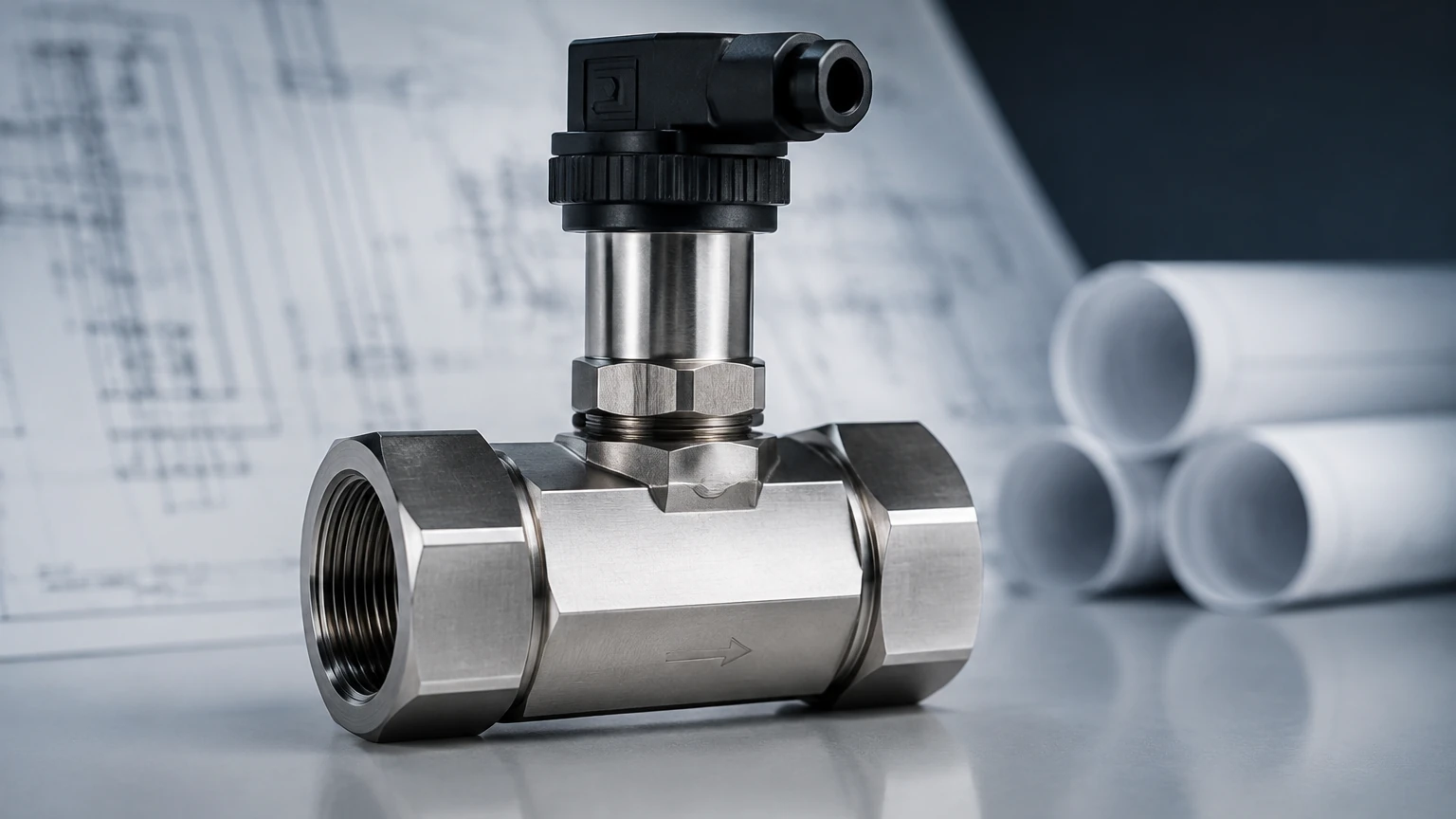
Proper installation is as important as selecting the right technology. An incorrectly installed in line flow switch will provide false readings or fail prematurely.
Straight Pipe Requirements
To ensure a stable flow profile, most switches require a minimum length of straight pipe upstream and downstream of the installation point. Generally, a distance of 5 to 10 times the pipe diameter (5-10D) upstream and 3 to 5 times the pipe diameter (3-5D) downstream is recommended. This minimizes turbulence caused by elbows, valves, or pumps.
Orientation
While some switches (like thermal and spring-loaded piston types) can be mounted in any orientation, paddle switches are often gravity-dependent. If a paddle switch is mounted in a vertical pipe with downward flow, the weight of the paddle might interfere with the set point. Always verify the manufacturer's orientation specifications.
Entrained Air and Debris
In liquid systems, air bubbles can cause thermal switches to trigger falsely, as air has different heat transfer properties than liquid. Similarly, in mechanical switches, suspended solids or "trash" in the line can jam a paddle or piston. Installing a Y-strainer upstream of a mechanical in line flow switch is a standard B2B best practice to protect the instrument.
Electrical Shielding
For electronic switches, especially thermal dispersion models, signal interference from nearby high-voltage equipment can affect performance. Using shielded cables and ensuring proper grounding of the instrument body is essential for maintaining signal integrity.
For industrial facilities managing complex fluid systems, coordinating flow detection with tank levels is often necessary. Reviewing comprehensive Main Page resources can help engineers select compatible level and flow instruments to build a unified monitoring architecture.
Limitations and Operational Risks
Despite their utility, in line flow switches have specific limitations that must be managed:
1. Scaling and Fouling: In hard water or wastewater applications, calcium deposits or biological growth can coat the sensing element. In thermal switches, this acts as an insulator, slowing response times. In mechanical switches, it can lead to sticking.
2. Minimum Flow Velocity: Every switch has a minimum threshold below which it cannot reliably detect movement. If the process requires monitoring extremely low velocities (e.g., leakage detection), a specialized low-flow thermal switch is usually the only viable option.
3. Pressure Drop: Mechanical switches, particularly the piston type, introduce a restriction in the pipe. Engineers must calculate the resulting pressure drop to ensure the pump can still meet the system's flow requirements.
4. Cavitation: If a flow switch is installed too close to a control valve or pump discharge, cavitation (the formation of vapor bubbles) can occur. This can erode the sensor or cause erratic switching behavior.
Frequently Asked Questions (FAQs)
Q: What is the difference between a flow meter and an in line flow switch?
A: A flow meter provides a continuous measurement of the flow rate (e.g., liters per minute), whereas a flow switch only indicates whether the flow is above or below a specific set point. Switches are typically used for safety interlocks, while meters are used for process monitoring and billing.
Q: Can an in line flow switch be used for both gas and liquid?
A: Thermal dispersion switches are often rated for both media, though they must be calibrated specifically for the density and thermal conductivity of the fluid in use. Mechanical paddle switches are generally ineffective for gas due to the low density of the medium.
Q: How do I adjust the set point on a mechanical flow switch?
A: Most mechanical switches feature an adjustment screw that changes the spring tension (on piston types) or the microswitch position (on paddle types). Turning the screw clockwise typically increases the flow rate required to trigger the switch.
Q: Are these devices suitable for hazardous areas?
A: Yes, many industrial in line flow switches are available with ATEX, IECEx, or UL certifications for use in explosive atmospheres. These models often utilize intrinsically safe circuits or explosion-proof housings.
Conclusion
The in line flow switch remains a cornerstone of industrial process safety. By understanding the nuances of thermal versus mechanical sensing and adhering to strict installation guidelines, engineering teams can significantly reduce the risk of equipment damage. Whether protecting a high-value pump in a water treatment plant or ensuring cooling flow in a chemical reactor, selecting the right switch requires a balance of fluid compatibility, mechanical robustness, and electrical requirements. For those designing integrated systems, consulting expert resources for both flow and level measurement ensures a more resilient and automated industrial operation.