Electromagnetic Water Meters
Electromagnetic Water Meters
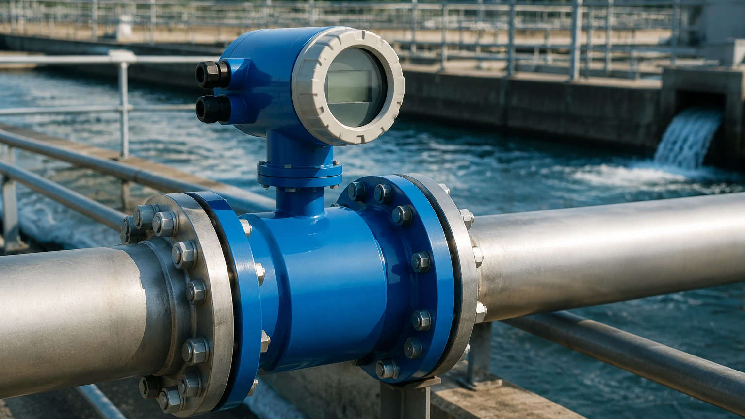
In the landscape of industrial process control and water management, electromagnetic water meters—often referred to as magmeters—have become the standard for measuring the flow of conductive liquids. Unlike mechanical meters that rely on moving parts, these instruments utilize electromagnetic properties to provide highly accurate, obstructionless measurement. For B2B stakeholders in water treatment, chemical processing, and industrial automation, understanding the technical nuances of these meters is essential for optimizing system efficiency and reducing maintenance costs.
Understanding the Measurement Principle: Faraday’s Law
The operation of electromagnetic water meters is based on Faraday’s Law of Electromagnetic Induction. This principle states that a conductor moving through a magnetic field produces an electrical voltage proportional to its velocity.
In the context of a flow meter, the "conductor" is the liquid itself. The meter consists of a non-magnetic tube lined with an insulating material. Two electromagnetic coils are placed outside or within the flow tube to generate a constant magnetic field ($B$) across the cross-section of the pipe. As a conductive liquid flows through this field at a certain velocity ($v$), it generates a voltage ($E$) that is picked up by two electrodes mounted flush with the pipe wall.
The relationship is defined by the formula:
E = k · B · D · v
* E: Induced voltage
* k: Instrument constant
* B: Magnetic field strength
* D: Inner diameter of the pipe
* v: Average velocity of the liquid
Because the magnetic field strength and the pipe diameter are constant, the induced voltage is directly proportional to the flow velocity. This linear relationship allows for high accuracy across a wide dynamic range (turn-down ratio), often exceeding 100:1.
Key Evaluation Criteria for Selection
Selecting the correct electromagnetic water meter requires a detailed analysis of the process fluid and the environmental conditions. Because the meter has no moving parts to wear out, the primary points of failure or inaccuracy usually stem from improper material selection or insufficient fluid conductivity.
Fluid Conductivity
For an electromagnetic water meter to function, the fluid must have a minimum conductivity, typically $\ge 5 \mu S/cm$. While most raw water, wastewater, and chemical solutions meet this threshold, magmeters cannot measure non-conductive fluids such as demineralized water, oil, or hydrocarbons.
Liner and Electrode Material Compatibility
The internal liner protects the meter body from the process fluid and prevents the induced voltage from shorting out against the metal pipe. Similarly, the electrodes must resist corrosion and abrasion.
Common Selection Table: Liner and Electrode Materials
| Component | Material | Typical Applications | Temperature Limits |
| :— | :— | :— | :— |
| Liner | PTFE (Teflon) | Highly corrosive chemicals, acids, bases | -40°C to +180°C |
| | Hard Rubber | General water treatment, wastewater | 0°C to +80°C |
| | PFA | High-temperature hygienic/food applications | -40°C to +150°C |
| | Polyurethane | Abrasive slurries, mining, wastewater | -20°C to +60°C |
| Electrode | SS316L | Clean water, mild chemicals | N/A |
| | Hastelloy C | Chlorine, seawater, oxidizing acids | N/A |
| | Tantalum | Highly aggressive acids (Hydrochloric) | N/A |
| | Titanium | Brine, chlorides, bleach | N/A |
Installation Guidelines and Best Practices
To maintain the accuracy specified by the manufacturer, electromagnetic water meters must be installed according to strict hydraulic guidelines. The most critical factor is ensuring a fully developed flow profile and a completely full pipe.
1. Straight Pipe Runs: To eliminate turbulence caused by valves, pumps, or bends, a minimum straight run of pipe is required. Generally, this is 5 times the nominal diameter (5D) upstream and 2 times the nominal diameter (2D) downstream of the meter.
2. Full Pipe Requirement: The meter must always be full of liquid. If the pipe is partially empty, the meter will over-read or provide unstable signals. Installation in a U-section or at the lowest point of a piping system is recommended to ensure the sensor remains flooded.
3. Grounding: Since the induced voltage is often in the millivolt range, electrical noise can easily interfere with the signal. Proper grounding is essential. For metal pipes, the meter is usually grounded to the pipe flanges. For plastic or lined pipes, grounding rings must be installed to establish an electrical connection with the fluid.
4. Flow Direction: While most modern magmeters are bi-directional, they should be installed following the arrow on the meter body to ensure the transmitter correctly interprets positive and negative flow.
Limitations and Common Operational Risks
While electromagnetic water meters are robust, they are not universal solutions. Engineers must account for the following limitations:
* Entrained Air: Large bubbles or high concentrations of entrained air will cause significant measurement errors. Air bubbles are non-conductive and disrupt the magnetic field interaction.
* Electrode Coating: In applications involving wastewater or oily residues, a film can build up over the electrodes. This "coating" insulates the electrode from the fluid, leading to signal loss. Some high-end meters feature electrode cleaning circuits or removable electrodes to mitigate this.
* Vacuum Conditions: Some liners, particularly PTFE, can collapse or peel away from the tube wall if the pipe is subjected to a vacuum. If vacuum conditions are possible (e.g., in a pump suction line), a vacuum-resistant liner like PFA or reinforced PTFE should be specified.
* Ambient Interference: High-power cables or large motors near the meter can create electromagnetic interference (EMI). Shielded cabling and dedicated grounding are required in industrial automation environments.
Integrating Flow and Level Measurement in Process Automation
In many industrial applications, flow measurement is only one part of the equation. For instance, in chemical dosing or water storage, monitoring the volume of liquid in a tank is just as critical as monitoring the rate at which it enters or leaves.
Integrating electromagnetic water meters with sophisticated level measurement systems allows for a comprehensive mass balance approach. While the magmeter tracks the volumetric flow through the piping, radar or ultrasonic level sensors provide real-time data on inventory. For organizations looking to optimize their entire liquid management chain, reviewing the comprehensive product options and application support available on our Main Page can provide the necessary technical context for selecting compatible instruments.
By combining high-accuracy flow data with reliable level measurement, plant operators can detect leaks, prevent tank overflows, and automate complex batching processes with greater precision.
Frequently Asked Questions (FAQs)
Q: Do electromagnetic water meters require regular calibration?
A: Because they have no moving parts, magmeters are very stable. However, in regulated industries or billing applications, annual wet calibration or electronic "dry" verification is often required to ensure the electronics and coils are performing within specification.
Q: Can these meters measure the flow of steam or gas?
A: No. Electromagnetic meters require a conductive liquid. Gases and steam are not sufficiently conductive to generate a measurable voltage in a magnetic field.
Q: What is the typical lifespan of an industrial magmeter?
A: With proper liner and electrode selection, an electromagnetic water meter can last 20 to 30 years. The primary limiting factor is usually the lifespan of the electronic transmitter, which may need upgrading after 10-15 years, while the primary sensor body remains in service.
Q: How do I handle measurement in pipes larger than 2000 mm?
A: For very large diameters, insertion-type electromagnetic meters can be used. These measure the velocity at a specific point in the pipe cross-section and calculate the total flow based on the pipe area, though they generally offer lower accuracy than full-bore meters.
Conclusion
Electromagnetic water meters represent a pinnacle of reliability for conductive fluid measurement. By eliminating mechanical wear and pressure drop, they offer a low total cost of ownership for B2B applications ranging from municipal water distribution to aggressive chemical processing. Successful implementation relies on a thorough understanding of Faraday's Law, disciplined installation practices, and the careful matching of liner and electrode materials to the specific chemical properties of the process fluid.