Flowine
Flowine
In the landscape of industrial fluid management, the term "flowine" refers to the integrated systems of piping, conduits, and channels used to transport liquids and slurries across a facility. Efficient flowine management is critical for maintaining process stability, ensuring safety, and optimizing resource utilization in industries ranging from water treatment to chemical processing. At the heart of these systems lies the need for precise level measurement, which provides the data necessary to control flow rates, prevent overflows, and monitor inventory.
Selecting the appropriate instrumentation for flowine applications requires a deep understanding of measurement principles, media characteristics, and environmental constraints. This guide explores the primary technologies used to monitor levels within flowine systems, offering engineering insights into their application and selection.
The Role of Level Measurement in Flowine Systems
Flowine systems are rarely static. They are subject to fluctuations in pressure, temperature, and flow velocity. Level measurement serves as a proxy for volume and flow in many scenarios, such as in open channel flow measurement or surge tank monitoring. By accurately determining the height of a liquid within a vessel or pipe, operators can derive critical process variables.
For instance, in wastewater treatment, monitoring the level in a flowine distribution box ensures that effluent is partitioned correctly between different treatment stages. In chemical manufacturing, level sensors in flowine headers prevent dry-running of pumps, which can lead to catastrophic equipment failure. The integration of reliable sensors into these systems is not merely a matter of convenience but a fundamental requirement for industrial automation.
Measurement Principles: Non-Contact Technologies
Non-contact level measurement is often preferred in flowine applications where the media is corrosive, viscous, or prone to scaling. By eliminating physical contact with the liquid, these sensors reduce maintenance requirements and extend service life.
Radar Level Measurement (FMCW)
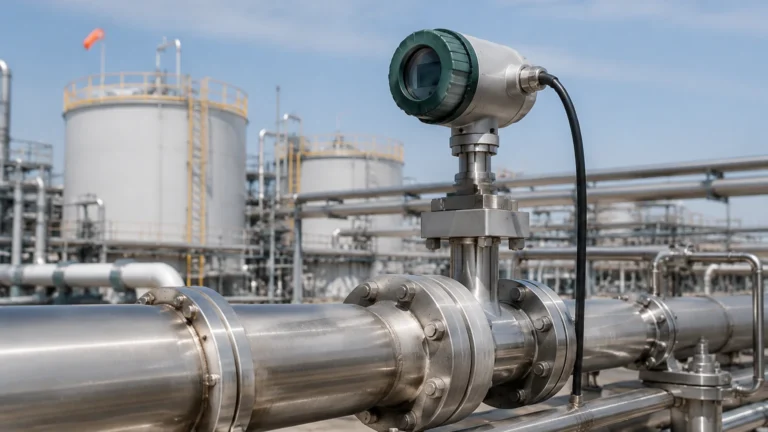
Radar level meters, particularly those utilizing Frequency Modulated Continuous Wave (FMCW) technology, are the gold standard for high-precision flowine monitoring. These devices emit a continuous signal with a constantly changing frequency. The signal reflects off the liquid surface and returns to the sensor. The frequency difference between the emitted and received signal is proportional to the distance.
Modern 80GHz radar sensors offer a narrow beam angle, which is essential for flowine systems with internal obstructions or narrow geometries. They are unaffected by changes in pressure, temperature, or the presence of vapors, making them ideal for volatile chemical storage or high-pressure pipelines.
Ultrasonic Level Sensors
Ultrasonic sensors operate on the Time-of-Flight (ToF) principle. The sensor emits an acoustic pulse that travels through the air, reflects off the liquid surface, and returns to the transducer. The distance is calculated based on the speed of sound.
While cost-effective, ultrasonic sensors are sensitive to environmental factors. The speed of sound changes with air temperature, requiring integrated temperature compensation. Furthermore, heavy foam or significant steam in the flowine can absorb the acoustic signal, leading to measurement errors. They are best suited for stable, ambient-pressure water applications.
Measurement Principles: Contact-Based Technologies
In scenarios where surface turbulence or foam renders non-contact methods unreliable, contact-based sensors provide a robust alternative.
Hydrostatic Level Transmitters
Hydrostatic measurement relies on the principle that the pressure at a specific point in a static liquid is proportional to the height of the liquid column above it. The formula used is $P = \rho \cdot g \cdot h$, where $P$ is pressure, $\rho$ is the density of the liquid, $g$ is gravity, and $h$ is the height.
In flowine applications, submersible hydrostatic sensors are often placed at the bottom of sumps or tanks. These sensors use a diaphragm to sense the pressure, which is then converted into a level reading. This method is highly reliable for liquids with constant density but requires recalibration if the liquid composition (and thus density) changes significantly.
Magnetic Level Gauges
For high-pressure or high-temperature flowine bypass applications, magnetic level gauges provide a clear visual indication and electronic feedback. A float containing a permanent magnet moves with the liquid level inside a bypass chamber. This magnet actuates a series of external flags or a continuous transmitter. Because the liquid is contained within a sealed chamber, this method is exceptionally safe for hazardous or toxic media.
Selection Criteria for Flowine Instrumentation
Choosing the right sensor for a flowine project involves evaluating several technical parameters. The following table provides a comparison of common technologies based on typical process conditions.
| Technology | Accuracy | Media Compatibility | Max Temperature | Pressure Range | Ideal Application |
| :— | :— | :— | :— | :— | :— |
| 80GHz Radar | ±1 mm | Corrosive, volatile | Up to 250°C | Up to 4.0 MPa | Narrow tanks, chemical reactors |
| Ultrasonic | ±0.25% FS | Water-based, non-foaming | Up to 80°C | Atmospheric | Open channels, sumps |
| Hydrostatic | ±0.1% FS | Slurries, oils, water | Up to 100°C | Varies by depth | Deep wells, vented tanks |
| Magnetic Gauge| ±5 mm | Clean liquids | Up to 400°C | Up to 16 MPa | Boiler drums, bypass pipes |
When evaluating a flowine system, engineers must confirm the dielectric constant (Dk) of the media for radar applications. Liquids with low Dk values (such as hydrocarbons) reflect less energy, potentially requiring specialized high-sensitivity radar units. For a comprehensive overview of available technologies, engineers can visit the Main Page to review product options and application support.
Installation and Engineering Best Practices
Proper installation is as critical as sensor selection. Even the most advanced radar or ultrasonic meter will fail if the installation environment is not accounted for.
1. Avoid the Dead Zone: Every sensor has a "blocking distance" or dead zone near the transducer face where measurements are impossible. Ensure the sensor is mounted high enough so the maximum liquid level never enters this zone.
2. Nozzle Geometry: For radar and ultrasonic sensors, the mounting nozzle should be as short and wide as possible. Long, narrow nozzles can create internal reflections (ringing) that mask the true level signal.
3. Turbulence Management: In flowine systems with high-velocity inflows, the liquid surface may be turbulent. Using a stilling well or a bypass pipe can stabilize the surface, allowing for a more accurate and consistent reading.
4. Beam Path Clearance: Ensure the sensor’s signal path is clear of ladders, pipes, or agitators. While modern software can "map out" fixed obstructions, it is better to avoid them during the design phase.
Limitations and Environmental Challenges
Flowine environments often present challenges that can interfere with signal integrity.
* Foam: Heavy, thick foam acts as an insulator for ultrasonic waves and can scatter radar signals. In such cases, a low-frequency radar or a contact-based method like a magnetic level gauge or hydrostatic transmitter is preferred.
* Condensation and Buildup: In humid flowine systems, condensation can form on the sensor face. Sensors with PTFE-coated antennas or "drip-off" designs help shed moisture. For sticky media that causes buildup, non-contact radar is generally superior to contact probes.
* Vessel Geometry: In horizontal cylindrical pipes or tanks used in flowine, the relationship between level and volume is non-linear. The level transmitter or the control system (PLC/DCS) must be programmed with a strapping table or linearization curve to provide accurate volume data.
Frequently Asked Questions (FAQ)
Q: Can radar level meters be used in plastic flowine tanks?
A: Yes. Radar signals can penetrate plastic and fiberglass. It is possible to mount a radar sensor above a closed plastic tank and measure the level through the roof, provided the material is not conductive and does not contain carbon black.
Q: How does temperature affect hydrostatic level measurement?
A: Temperature affects the density of the liquid. Since hydrostatic pressure is density-dependent, significant temperature swings can introduce errors. Some advanced hydrostatic transmitters include integrated temperature sensors to compensate for these changes.
Q: What is the maximum range for ultrasonic flowine sensors?
A: Typically, industrial ultrasonic sensors have a range of up to 15 or 20 meters. However, as the distance increases, the signal strength decreases and the beam spreads, making the sensor more susceptible to interference from tank walls or internal structures.
Q: Is it necessary to recalibrate sensors for different liquids?
A: For radar and ultrasonic sensors, calibration is based on distance, so the liquid type does not usually require recalibration (unless the Dk value is extremely low). For hydrostatic sensors, recalibration is necessary if the density of the liquid changes.
Conclusion
Effective flowine management depends on the integration of accurate, reliable level measurement instruments. By understanding the physics behind radar, ultrasonic, and hydrostatic technologies, engineers can select the solution that best fits their specific process conditions. Whether dealing with the corrosive environments of chemical processing or the high-volume demands of water treatment, the right instrumentation ensures that flowine systems operate at peak efficiency with minimal downtime. For detailed technical specifications and assistance in selecting the right instrument for your project, please refer to the Main Page for expert guidance.