Gas Flow Monitor
Gas Flow Monitor
In industrial process control, the ability to accurately measure and record the movement of gases is fundamental to safety, efficiency, and cost management. A gas flow monitor serves as the primary interface between the physical process and the control system, providing real-time data on consumption, leakage, and process stability. Whether managing compressed air systems, monitoring natural gas lines, or controlling inert gas blanketing in chemical storage, selecting the correct monitoring technology requires a deep understanding of fluid dynamics and instrument physics.
Industrial gas flow monitoring differs significantly from liquid flow measurement due to the compressibility of gases. Changes in temperature and pressure directly alter the density and volume of the gas, necessitating sophisticated compensation methods or the use of mass-flow-based technologies. This guide explores the core principles, selection criteria, and installation requirements for modern gas flow monitoring systems.
Core Measurement Principles
Before selecting a gas flow monitor, engineers must evaluate which physical principle best suits the specific gas properties and process conditions. The most common technologies include thermal mass, differential pressure, vortex shedding, and ultrasonic measurement.
Thermal Mass Measurement
Thermal mass flow monitors operate on the principle of heat transfer. Typically, the sensor consists of two RTD (Resistance Temperature Detector) elements. One serves as a reference, measuring the ambient gas temperature, while the other is heated to a constant differential temperature above the reference. As gas flows past the heated sensor, it carries away heat. The electrical power required to maintain the temperature differential is directly proportional to the mass flow rate of the gas.
This technology is highly valued because it measures mass flow directly without needing external pressure or temperature compensation. It is particularly effective for low-flow applications and detecting leaks in compressed air systems.
Differential Pressure (DP)
Differential pressure remains one of the most widely used methods in heavy industry. It relies on Bernoulli’s principle: as gas passes through a constriction (such as an orifice plate, Venturi tube, or Pitot tube), its velocity increases and its pressure decreases. The square root of the pressure drop ($\\Delta P$) across the constriction is proportional to the flow rate.
While robust and well-understood, DP-based gas flow monitors require secondary sensors for pressure and temperature to calculate the compensated mass flow, as the volume of gas varies with process conditions.
Vortex Shedding
Vortex flow meters utilize the Von Kármán effect. When gas flows past a non-streamlined "shredder bar" placed in the stream, vortices are shed alternately from each side. The frequency of these vortices is directly proportional to the velocity of the gas. This method is excellent for high-velocity gas and steam applications where there are no moving parts to wear out, though it requires a minimum Reynolds number to function accurately.
Ultrasonic Transit-Time
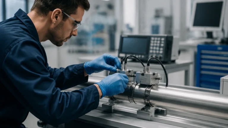
Ultrasonic monitors use sound waves to determine gas velocity. Transducers send pulses across the pipe at an angle. The pulse traveling with the flow moves faster than the pulse traveling against it. The difference in transit time is used to calculate the flow velocity. This technology is non-intrusive, offers a high turndown ratio, and causes zero pressure drop, making it ideal for large-diameter natural gas pipelines.
Key Selection Criteria for Industrial Applications
Choosing a gas flow monitor is not a "one-size-fits-all" process. Engineers must define the following parameters to ensure long-term reliability:
1. Gas Composition: Is the gas clean, dry, corrosive, or explosive? For example, thermal mass meters require a known gas composition because different gases have different thermal conductivities. If the gas mixture changes, the calibration becomes invalid.
2. Flow Range and Turndown Ratio: The turndown ratio is the range between the maximum and minimum measurable flow. If a process has high seasonal variance, a monitor with a 100:1 turndown (like thermal mass) is superior to an orifice plate (typically 4:1).
3. Process Conditions: High-temperature or high-pressure environments may exclude certain sensor types. Always verify the wetted materials are compatible with the gas to prevent corrosion or hydrogen embrittlement.
4. Accuracy vs. Repeatability: In custody transfer, absolute accuracy (e.g., ±0.5%) is critical. In simple process control or leak detection, repeatability may be more important than absolute accuracy.
Technology Comparison Table
| Technology | Primary Advantage | Best For | Typical Turndown | Pressure Drop |
| :— | :— | :— | :— | :— |
| Thermal Mass | Direct mass flow measurement | Compressed air, N2, CO2 | 100:1 | Negligible |
| Vortex | No moving parts, durable | Steam, high-speed gas | 20:1 | Moderate |
| DP (Orifice) | Low cost, well-standardized | Large pipes, high pressure | 4:1 | High |
| Ultrasonic | Non-intrusive, high accuracy | Natural gas, large ducts | 50:1 | Zero |
Installation and Engineering Considerations
Even the most advanced gas flow monitor will fail to provide accurate data if installed incorrectly. Gas flow profiles must be fully developed and stable for the sensor to record a representative velocity.
Straight Pipe Requirements
Most flow monitors require a specific length of straight pipe upstream and downstream of the sensor to eliminate turbulence caused by elbows, valves, or reducers. A common rule of thumb is 10 to 20 diameters (D) of straight pipe upstream and 5D downstream. If space is limited, flow conditioners or honeycombs may be installed to artificially straighten the flow.
Orientation and Moisture
In gas applications, moisture is a significant enemy. If a gas stream contains water vapor, condensation can collect on the sensor or in the impulse lines of a DP meter. For horizontal pipes, gas flow monitors should generally be installed on the top or side of the pipe to prevent liquid condensate from entering the sensor housing. If the gas is "wet," specialized separators or heated sensors may be necessary.
Calibration and Scaling
Gas flow is often reported in "Standard" or "Normal" units, such as Nm³/h (Normal cubic meters per hour) or SCFM (Standard Cubic Feet per Minute). These units refer to the volume the gas would occupy at a specific reference temperature and pressure (e.g., 0°C and 1.013 bar). It is vital to confirm that the monitor's internal scaling matches the site's reporting standards to avoid significant mass balance errors.
Common Risks and Limitations
* Pressure Drop: Instruments like orifice plates create a permanent pressure loss in the system. Over time, the energy cost of the compressors working to overcome this drop can exceed the initial cost of a more expensive, low-pressure-drop meter like an ultrasonic or thermal mass monitor.
* Particulate Contamination: In "dirty" gas applications (like flare gas or biogas), particulates can coat sensors or erode orifice plates. Regular maintenance and the use of non-clogging designs, such as certain vortex or ultrasonic models, are required.
* Calibration Drift: Over time, sensors may drift due to electronic aging or physical wear. In critical B2B environments, annual field verification or laboratory calibration is recommended to maintain compliance with ISO standards.
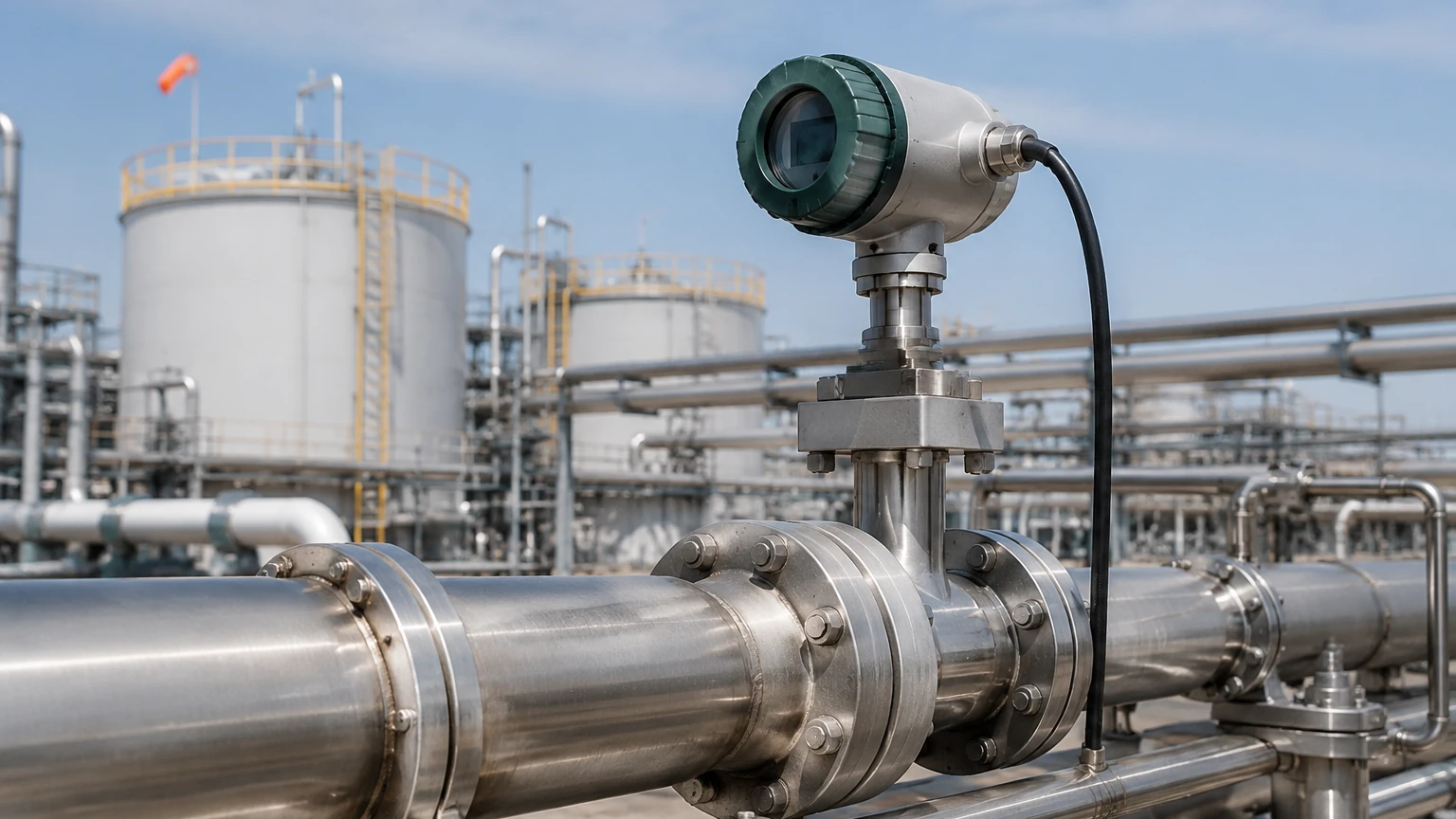
Integrating Gas Flow with Level Measurement
In many industrial setups, gas flow monitoring is used in conjunction with level measurement systems. For example, in pressurized chemical storage tanks, a gas flow monitor tracks the nitrogen used for blanketing, while a radar level meter tracks the liquid volume. Understanding the total mass balance of a vessel requires data from both systems. For professionals looking to optimize their entire tank farm or process plant, reviewing the comprehensive range of level and flow instruments on the Main Page can provide insights into integrated automation solutions.
Frequently Asked Questions (FAQ)
Q: What is the difference between Actual Flow and Standard Flow?
A: Actual flow (ACFM or m³/h) is the volume of gas at its current temperature and pressure. Standard flow (SCFM or Nm³/h) is the volume the gas would occupy at a standard reference point. Since gas is compressible, standard flow is the only way to compare gas quantities across different process stages.
Q: Can a gas flow monitor measure steam?
A: Not all of them. Steam is particularly harsh due to its high temperature and potential for "water hammer." Vortex meters are the industry standard for steam flow, whereas thermal mass meters are generally unsuitable for steam.
Q: How do I handle gas mixtures with changing concentrations?
A: If the gas composition is not constant, technologies that rely on gas properties (like thermal mass) will require a gas chromatograph input or should be replaced by technologies that are independent of composition, such as ultrasonic or vortex meters.
Q: Is a gas flow monitor necessary for compressed air?
A: Yes. Compressed air is one of the most expensive utilities in a factory. Monitoring flow allows for the detection of leaks, which often account for 20-30% of a plant's total energy consumption.
Conclusion
A reliable gas flow monitor is more than just a measurement tool; it is a critical component for operational safety and environmental compliance. By understanding the physics of the gas—whether it is the heat-carrying capacity in thermal systems or the velocity-induced frequency in vortex systems—engineers can select a device that provides long-term stability. When combined with accurate level measurement and robust control logic, gas flow monitoring ensures that industrial processes remain efficient, predictable, and cost-effective. For further technical specifications and product selection support, engineers should consult the Main Page to explore the full spectrum of industrial measurement technologies.