Liquid Level Detection Machine
Liquid Level Detection Machine
In the landscape of industrial automation, a liquid level detection machine is rarely a single standalone device. Instead, it represents an integrated system of sensors, transmitters, and signal processing units designed to provide real-time data on the volume or height of fluids within a vessel. Whether managing volatile chemicals, wastewater, or food-grade oils, the selection of the correct detection technology is critical for operational safety, inventory accuracy, and process efficiency.
Selecting the appropriate liquid level detection machine requires a deep understanding of the physical properties of the media, the environmental conditions of the storage vessel, and the specific requirements of the control system. This guide examines the core measurement principles used in modern industrial instrumentation, provides selection frameworks, and outlines best practices for installation and maintenance.
Measurement Principles of Level Detection Systems
Before selecting a liquid level detection machine, engineers must evaluate the physics of the measurement. Most industrial applications utilize one of four primary technologies: radar, ultrasonic, hydrostatic, or magnetic.
1. Radar Level Measurement (ToF)
Radar instruments use Time-of-Flight (ToF) technology. The device emits high-frequency electromagnetic waves (typically in the 26 GHz or 80 GHz range) that travel to the liquid surface and reflect back to the sensor.
* Non-Contact Radar: These sensors are ideal for corrosive or hygienic applications because they do not touch the media. The 80 GHz radar is particularly effective due to its narrow beam angle, which allows it to avoid internal tank obstructions like agitators or heating coils.
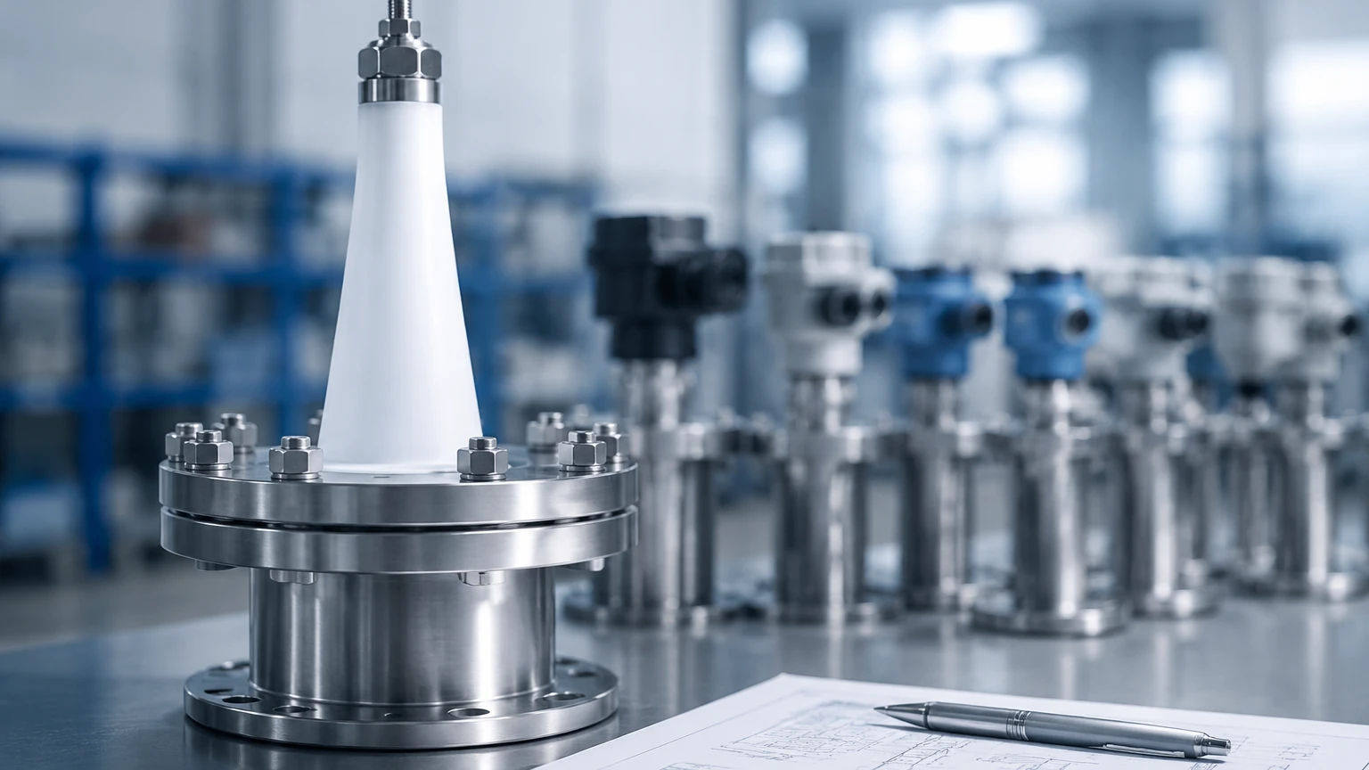
* Guided Wave Radar (GWR): This variation uses a probe (cable or rod) to guide the signal. GWR is highly effective in low-dielectric liquids or applications with heavy foam, as the probe ensures the signal reaches the liquid surface without significant scattering.
2. Ultrasonic Level Sensors
Ultrasonic detection machines function similarly to radar but use sound waves instead of electromagnetic pulses. The sensor emits an ultrasonic pulse that bounces off the liquid surface. The time taken for the echo to return is proportional to the distance.
Because sound requires a medium to travel, ultrasonic sensors cannot be used in a vacuum. Furthermore, fluctuations in air temperature can change the speed of sound, necessitating integrated temperature compensation within the sensor housing. These are generally cost-effective solutions for water and wastewater management.
3. Hydrostatic Level Transmitters
Hydrostatic measurement is based on the principle that the pressure at the bottom of a tank is directly proportional to the height of the liquid column above it. The formula used is $P = \rho \cdot g \cdot h$, where $P$ is pressure, $\rho$ is the density of the liquid, $g$ is gravity, and $h$ is the height.
These systems are robust and simple to install, often involving a submersible probe or a flange-mounted pressure transmitter at the base of the tank. However, if the density of the liquid changes (due to temperature or concentration shifts), the measurement will require recalibration.
4. Magnetic Level Gauges
For high-pressure and high-temperature applications, magnetic level gauges provide a mechanical, highly visible solution. A float containing a permanent magnet moves with the liquid level inside a bypass chamber. This magnet flips external rollers or flags to show the level visually and can be paired with a reed switch or transmitter for electronic data output.
Technical Selection Criteria
Choosing the right liquid level detection machine involves more than just matching a sensor to a tank. The following table provides a comparison of common technologies to assist in the initial engineering phase.
| Technology | Accuracy | Media Suitability | Temperature Range | Pressure Range | Typical Applications |
| :— | :— | :— | :— | :— | :— |
| 80GHz Radar | ±1 mm | Most liquids/solids | -40°C to +200°C | Up to 40 bar | Chemical reactors, oil storage |
| Ultrasonic | ±0.25% FS | Water-based liquids | -40°C to +80°C | Atmospheric | Open channels, sumps |
| Hydrostatic | ±0.1% FS | Homogeneous fluids | -20°C to +100°C | Depth dependent | Deep wells, water tanks |
| Guided Wave | ±2 mm | Low dielectric fluids | -50°C to +400°C | Up to 400 bar | Steam drums, LPG storage |
When evaluating a liquid level detection machine, engineers must confirm the following variables:
1. Dielectric Constant ($ε_r$): Crucial for radar; lower values reflect less signal.
2. Vapor and Dust: High concentrations can attenuate ultrasonic signals but rarely affect radar.
3. Agitation: Surface turbulence may require the use of a stilling well or a software-based damping filter.
4. Chemical Compatibility: The wetted parts (e.g., PTFE, Stainless Steel 316L, Hastelloy) must resist corrosion from the process media.
Installation and Engineering Considerations
Proper installation is as important as the technology itself. Even the most advanced liquid level detection machine will fail if positioned incorrectly.
Dead Zones and Blocking Distances
Every sensor has a "dead zone" (or blocking distance) directly beneath the sensor face where measurement is impossible. For ultrasonic sensors, this is typically between 200mm and 600mm. If the tank overfills into this zone, the sensor may report an incorrect "full" or "empty" state. Engineers must ensure the sensor is mounted high enough to account for the maximum possible liquid level.
Nozzle Geometry
When mounting sensors on tank nozzles, the nozzle height and diameter must be considered. If a nozzle is too narrow or too long, the signal (especially ultrasonic or radar) may reflect off the nozzle walls before reaching the liquid, creating "false echoes." Using an extension or a sensor with a narrower beam angle can mitigate this.
Avoiding Obstructions
Internal structures such as ladders, pipes, and agitator blades are common sources of interference. While modern digital transmitters offer "false signal suppression" to map out these fixed reflections, it is best practice to install the sensor in a location with a clear line of sight to the liquid surface. The sensor should typically be placed 1/6th to 1/3rd of the tank diameter away from the wall to avoid side-wall interference.
Limitations and Operational Risks
While industrial level meters are highly reliable, they are not universal. Understanding their limitations prevents process failures.
* Foam Interference: Thick, dense foam can absorb ultrasonic and radar signals. In such cases, Guided Wave Radar or Hydrostatic transmitters are preferred as they are less affected by surface conditions.
* Vacuum Conditions: Ultrasonic waves cannot travel in a vacuum. For vacuum distillation columns, radar or magnetic gauges are the standard.
* Density Shifts: Hydrostatic sensors rely on constant density. If a process involves mixing different fluids or significant temperature swings that change the fluid density, the level reading will drift unless a dual-pressure differential system or a density-independent sensor (like radar) is used.
Frequently Asked Questions (FAQ)
Q: How often should a liquid level detection machine be calibrated?
A: For non-critical water storage, annual inspection is usually sufficient. However, in regulated industries like pharmaceuticals or oil and gas, semi-annual or quarterly calibration is often required to maintain safety and billing accuracy.
Q: Can one machine measure both liquid level and interface?
A: Yes. Guided Wave Radar is specifically designed to detect both the total level and the interface between two liquids (e.g., oil and water), provided the upper liquid has a lower dielectric constant than the lower liquid.
Q: What is the advantage of 80 GHz radar over 26 GHz radar?
A: The 80 GHz radar has a much shorter wavelength, resulting in a narrower beam and a smaller antenna size. This makes it easier to install in small tanks and more capable of avoiding internal obstructions.
Conclusion
Implementing an effective liquid level detection machine requires balancing technical capability with the practical realities of the industrial environment. By understanding the measurement principles—from the electromagnetic reflections of radar to the pressure-based calculations of hydrostatic sensors—facilities can ensure long-term reliability and accuracy.
For a comprehensive overview of available technologies and technical specifications, engineers can visit the Main Page to compare different instrument models and access application-specific support. Proper selection, combined with rigorous installation standards, remains the most effective way to prevent costly overflows, dry-run pump damage, and inventory discrepancies.