Pneumatic Level Controller
Pneumatic Level Controller
In the landscape of industrial process automation, the pneumatic level controller remains a cornerstone technology, particularly in sectors where electronic instrumentation faces significant environmental or safety challenges. While modern digital sensors have become more prevalent, the inherent reliability, simplicity, and intrinsic safety of pneumatic systems ensure their continued relevance in oil and gas, chemical processing, and offshore applications. This guide provides a technical overview of pneumatic level control systems, their operating principles, selection criteria, and practical installation considerations for engineering professionals.
Understanding the Measurement Principles
A pneumatic level controller functions by converting a change in liquid level into a proportional change in air pressure. This output signal, typically standardized at 0.2 to 1.0 bar (3 to 15 psi), is then used to actuate a control valve or trigger an alarm. Unlike electronic sensors that rely on microprocessors, pneumatic controllers use mechanical force balance or motion balance mechanisms.
The Displacement Principle
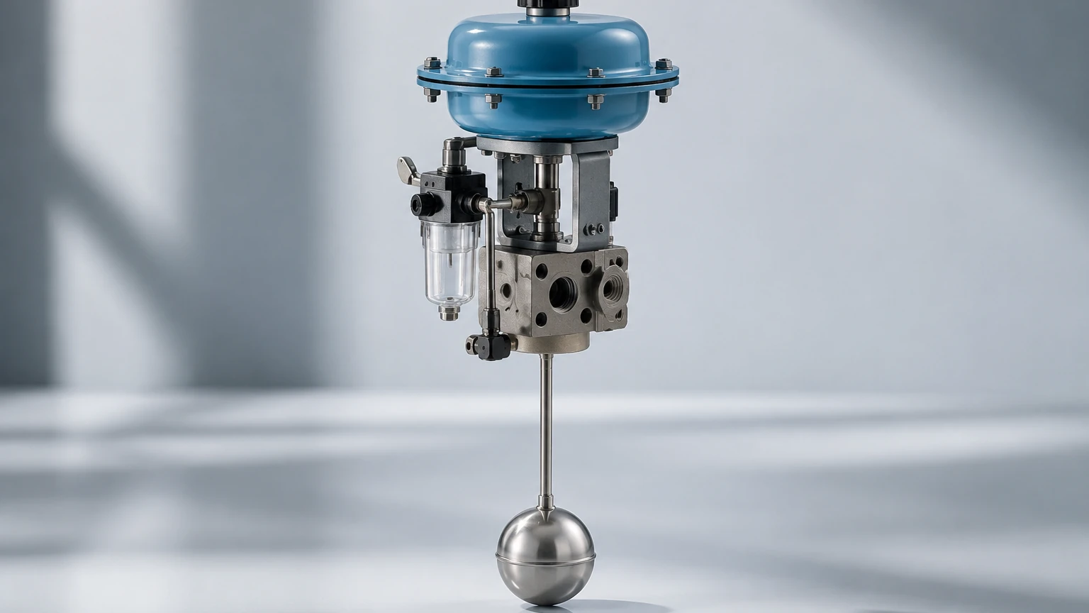
Most high-performance pneumatic level controllers utilize the displacement principle (Archimedes' Principle). A cylindrical displacer, which is heavier than the liquid, is suspended in the process fluid. As the liquid level rises, the buoyant force on the displacer increases, effectively reducing its apparent weight. This change in force is transmitted through a torque tube or a flexure tube to the controller mechanism.
The Flapper-Nozzle Assembly
The heart of the pneumatic controller is the flapper-nozzle assembly. The mechanical movement from the displacer moves a "flapper" closer to or further away from a small air nozzle.
1. Air Supply: A constant supply of clean, dry instrument air is fed to the nozzle through a restriction.
2. Backpressure: When the flapper is close to the nozzle, air flow is restricted, causing backpressure to build up.
3. Signal Conversion: This backpressure is amplified by a pneumatic relay to produce the final 0.2–1.0 bar (3–15 psi) output signal.
Proportional and Reset Action
Advanced pneumatic controllers offer proportional-only or proportional-plus-reset (PI) control. The proportional band determines how much the liquid level must change to move the output from 3 to 15 psi. The reset (integral) action eliminates the "offset" or steady-state error, ensuring the level returns exactly to the setpoint regardless of load changes.
Key Components of a Pneumatic Level System
To ensure a reliable control loop, several components must work in unison. While manufacturers like Welk provide a wide array of electronic alternatives on their Main Page, understanding the mechanical components of a pneumatic loop is essential for maintenance and legacy system integration.
1. The Displacer/Float: The primary sensing element. Displacers are used for continuous control, while floats are more common for simple on/off switching.
2. The Controller Head: Contains the flapper-nozzle, pneumatic relay, and adjustment knobs for setpoint and proportional band.
3. Air Filter Regulator (AFR): Essential for reducing plant air pressure (typically 7–10 bar) to the stable 1.4 bar (20 psi) required by the controller.
4. Pneumatic Control Valve: The final control element that physically adjusts the flow of liquid into or out of the vessel based on the controller's signal.
Selection Criteria and Technical Specifications
Selecting the correct pneumatic level controller requires a detailed analysis of the process fluid and the vessel environment. Engineers should use the following table as a baseline for evaluation:
Selection Table: Pneumatic Level Control Parameters
| Feature | Specification / Requirement | Engineering Consideration |
| :— | :— | :— |
| Process Fluid SG | 0.2 to 1.5 Specific Gravity | Displacer sizing must match fluid density. |
| Pressure Rating | Up to 170 bar (2500 psi) | Higher pressures require thicker torque tubes. |
| Temperature Range | -196°C to +450°C | Extreme temperatures require cooling fins or extensions. |
| Output Signal | 0.2–1.0 bar (3–15 psi) | Industry standard for pneumatic instrumentation. |
| Wetted Materials | SS316, Monel, Hastelloy | Must be chemically compatible with the process. |
| Control Type | Proportional or Snap-Action | Snap-action is used for dump valve applications. |
Material Compatibility
In chemical applications, the choice of wetted materials is critical. For corrosive environments involving acids or chlorides, SS316 is the standard, though exotic alloys like Hastelloy C may be required for high-temperature acidic service. The non-wetted parts, such as the controller housing, should ideally be aluminum with a corrosion-resistant coating or stainless steel for offshore environments.
Installation and Commissioning Guidelines
Proper installation is the most significant factor in the longevity of a pneumatic level controller. Unlike non-contact radar or ultrasonic sensors available at the Main Page, pneumatic displacers are intrusive and mechanical, requiring specific mounting orientations.
Mounting Configurations
* Side-Mounted: The controller is mounted to the side of the vessel using a flange or NPT connection. This is common for small vessels.
* External Cage: The displacer is housed in a separate chamber (cage) piped to the side of the vessel. This allows for maintenance and isolation without depressurizing the main tank.
* Top-Mounted: The displacer hangs directly into the tank from a top flange. This is used when side access is restricted.
Air Supply Quality
Pneumatic controllers are sensitive to contaminants. The air supply must meet ISO 8573-1 Class 2.4.1 standards:
* Particles: No larger than 40 microns.
* Moisture: Pressure dew point must be at least 10°C (18°F) below the lowest ambient temperature.
* Oil: Maximum concentration of 0.01 mg/m³.
Failure to provide clean air leads to nozzle clogging and relay failure, which are the most common causes of controller malfunction.
Calibration Steps
1. Zero Adjustment: With the liquid at the lowest desired level (or the displacer dry), adjust the nozzle position until the output signal is 0.2 bar (3 psi).
2. Span/Proportional Band Adjustment: Raise the level to the 100% mark and adjust the proportional band until the output reaches 1.0 bar (15 psi).
3. Repeatability Check: Cycle the level several times to ensure the mechanical linkages are not binding.
Operational Risks and Maintenance Requirements
While pneumatic controllers are robust, they are not "set and forget" devices. They involve moving parts and air consumption that require periodic oversight.
Common Risks
* Mechanical Binding: In dirty or viscous fluids, the displacer or torque tube can become coated in debris, leading to sluggish response or a stuck signal.
* Air Leaks: Even small leaks in the signal tubing can cause significant control offsets or prevent the control valve from opening fully.
* Vibration: High-frequency vibration in the piping can wear out the flapper-nozzle interface prematurely.
Maintenance Checklist
* Monthly: Check the air filter regulator for moisture or oil buildup. Drain the filter bowl.
* Quarterly: Inspect the flapper and nozzle for signs of erosion or salt buildup.
* Annually: Perform a full calibration check and inspect the torque tube for signs of fatigue or corrosion.
Comparison: Pneumatic vs. Electronic Level Control
For many modern facilities, the question arises: should we stick with a pneumatic level controller or upgrade to an electronic system?
| Feature | Pneumatic Controller | Electronic (Radar/Ultrasonic) |
| :— | :— | :— |
| Power Source | Compressed Air | 24V DC / 4-20mA Loop |
| Safety | Intrinsic (No sparks) | Requires Explosion-Proof Housing |
| Maintenance | Mechanical/Pneumatic skill | Electronic/Software skill |
| Data Integration | Difficult (Requires P/I converters) | Native (HART, Modbus, Profibus) |
| Accuracy | ±1.0% to 5.0% | ±1mm to ±5mm |
In remote locations without stable electrical grids, or in highly explosive zones where cabling costs are prohibitive, the pneumatic controller is often the more cost-effective choice. However, for precision and integration with a Distributed Control System (DCS), the advanced instruments found on the Main Page offer superior performance.
Frequently Asked Questions (FAQ)
Q: Can a pneumatic level controller be used for interface measurement (e.g., oil and water)?
A: Yes. By sizing the displacer specifically for the difference in specific gravities between the two liquids, the controller can accurately track the interface level while ignoring the total level.
Q: What is "snap-action" in a pneumatic controller?
A: Snap-action is a non-throttling control mode. The controller stays at 0 psi until a setpoint is reached, then immediately jumps to full supply pressure. This is typically used for "dumping" liquid from a separator into a storage tank.
Q: How far can the pneumatic signal be transmitted?
A: Generally, pneumatic signals should not be transmitted more than 100 meters (328 feet) due to signal lag (hysteresis). For longer distances, a pneumatic-to-current (P/I) converter should be used to transmit an electrical signal.
Q: Does temperature affect the accuracy of the controller?
A: Yes. Changes in temperature can change the density (SG) of the process fluid, which affects the buoyant force on the displacer. High-precision applications may require temperature compensation or recalibration for different seasonal operating temperatures.
Conclusion
The pneumatic level controller remains a vital tool for industrial level management, offering a level of ruggedness and simplicity that electronic devices struggle to match in specific niches. By understanding the mechanical principles of displacement and the nuances of the flapper-nozzle mechanism, engineers can ensure stable and safe process control. For applications requiring higher precision, digital output, or non-contact measurement, exploring the full range of modern technologies on the Main Page is recommended to find the optimal balance between legacy reliability and modern efficiency.