Thermal Mass Flow Meter
Thermal Mass Flow Meter
Thermal mass flow meters have become a cornerstone in industrial gas flow measurement, providing high-precision data without the need for complex pressure and temperature compensation. Unlike volumetric flow meters, which measure the space a fluid occupies, a thermal mass flow meter measures the molecular mass of the gas moving through a conduit. This distinction is critical in industrial applications where gas density fluctuates due to process variations. This guide provides a comprehensive technical overview of the principles, selection criteria, and installation requirements for thermal mass flow technology in B2B industrial environments.
Measurement Principles and Physics
The operation of a thermal mass flow meter is based on the physical principle of thermal dispersion or convective heat transfer. Specifically, most modern instruments utilize "King’s Law," which describes the relationship between the heat lost by a heated wire and the velocity of the fluid passing over it.
The RTD Sensor Configuration
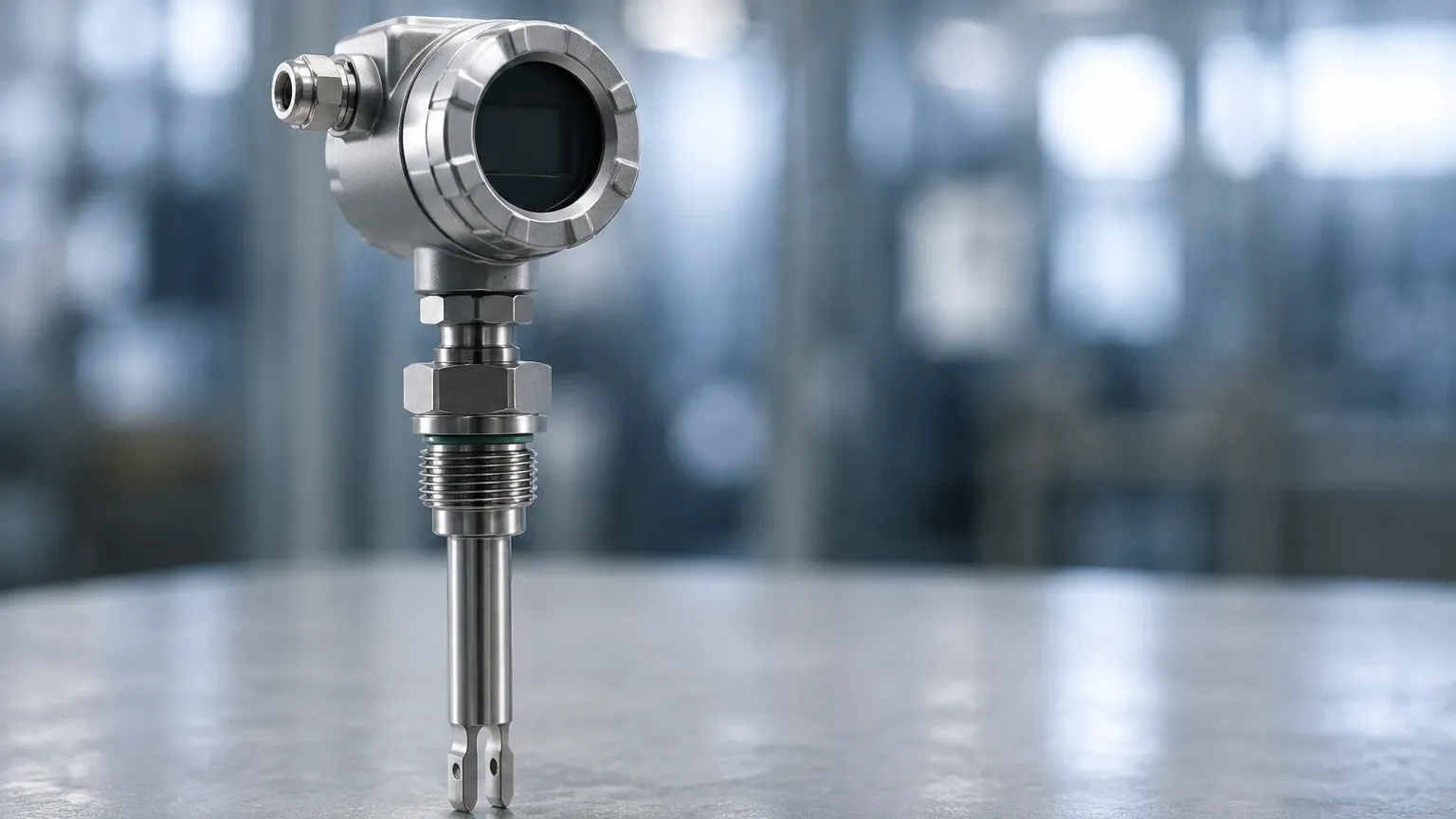
At the heart of the instrument are two Resistance Temperature Detectors (RTDs). These are typically platinum-wound sensors protected by a stainless steel or Hastelloy thermowell.
1. Reference Sensor: This RTD measures the actual temperature of the process gas. It provides a baseline for the electronics to understand the ambient conditions of the fluid.
2. Active (Heated) Sensor: This RTD is supplied with electrical current to maintain a specific temperature higher than that of the reference sensor.
As gas flows past the heated sensor, the gas molecules carry heat away—a process known as convective cooling. The rate at which this heat is dissipated is directly proportional to the mass flow rate of the gas. Because gas molecules are the medium of heat transfer, the instrument is effectively counting the number of molecules passing the sensor, regardless of the gas pressure or volume.
Constant Temperature Differential Method
The most common industrial implementation is the Constant Temperature Differential method. The instrument’s electronics vary the power delivered to the active sensor to maintain a constant temperature difference (ΔT) between the heated sensor and the reference sensor. As flow increases, more power is required to maintain this ΔT. The amount of electrical power consumed is then converted into a linear mass flow signal. This method is preferred for its wide turndown ratio and fast response times.
Design Variations: Insertion vs. Inline
When selecting a thermal mass flow meter, engineers must choose between two primary mechanical configurations based on the pipe size and the required accuracy.
Insertion Thermal Mass Flow Meters
Insertion meters are designed for large-diameter pipes and ducts, typically ranging from 50 mm (2 inches) to several meters in diameter. The sensor probe is inserted through a flange or a compression fitting into the center of the flow stream.
* Advantages: Lower cost for large pipes, ease of installation (often via hot-tapping without shutting down the process), and minimal pressure drop.
* Limitations: Accuracy is dependent on the flow profile being fully developed at the point of measurement.
Inline Thermal Mass Flow Meters
Inline meters consist of a flow body that is integrated directly into the piping system via flanged or NPT connections. These are typically used for smaller pipes, from 6 mm (1/4 inch) up to 100 mm (4 inches).
* Advantages: Higher accuracy due to the inclusion of built-in flow conditioners that stabilize the velocity profile before the gas reaches the sensors.
* Limitations: Higher pressure drop compared to insertion models and higher cost for larger pipe sizes.
Technical Selection Criteria
Choosing the right thermal mass flow meter requires a detailed understanding of the process gas and the environmental conditions. The following table outlines the primary evaluation criteria for industrial procurement.
| Parameter | Requirement | Engineering Consideration |
| :— | :— | :— |
| Gas Composition | Pure gas or known mixture | Specific heat capacity ($C_p$) must be known for accurate calibration. |
| Flow Range | Min/Max Flow | Thermal meters offer turndown ratios up to 100:1 or higher. |
| Pipe Diameter | 6 mm to 5000+ mm | Determines whether an inline or insertion model is appropriate. |
| Operating Pressure | Up to 60 bar (typical) | High-pressure applications require specialized sensor seals. |
| Temperature Range | -40°C to +200°C (standard) | High-temperature versions are available for stack gas monitoring. |
| Accuracy | ±1% of reading | Accuracy often depends on the stability of the gas composition. |
The Importance of Specific Heat ($C_p$)
Because thermal mass flow meters rely on heat transfer, the thermal properties of the gas—specifically its specific heat—are fundamental. A meter calibrated for Nitrogen will not provide accurate readings for Hydrogen or Carbon Dioxide without recalibration or the application of a conversion factor. In B2B applications involving mixed gases (e.g., biogas or flare gas), the exact percentage of each component must be confirmed before the instrument is manufactured.
Industrial Applications
Thermal mass flow meters are versatile instruments used across various sectors where gas measurement is critical for efficiency and safety.
1. Compressed Air Management: In manufacturing plants, compressed air is a significant utility cost. Thermal meters detect leaks and monitor consumption at individual branch lines to optimize compressor performance.
2. Wastewater Treatment (Aeration): Biological treatment processes require precise amounts of air to be pumped into aeration basins. Thermal meters provide the necessary control to ensure bacteria have enough oxygen without wasting energy on over-aeration.
3. Natural Gas Monitoring: Used for sub-metering in industrial boilers and furnaces to track energy efficiency and carbon emissions.
4. Semiconductor Manufacturing: High-purity gas delivery systems require the extreme low-flow sensitivity that only thermal mass technology can provide.
5. Biogas Production: Measuring gas output from anaerobic digesters, where flow rates can be very low and pressures are minimal.
For engineers looking to integrate these flow measurements with storage tank monitoring, the Welk Main Page offers a range of complementary level measurement solutions that work alongside flow data to provide a complete picture of process inventory.
Installation Considerations and Best Practices
To achieve the stated accuracy of a thermal mass flow meter, proper installation is paramount. The most common cause of measurement error is an irregular flow profile caused by upstream piping disturbances.
Straight Run Requirements
Like most flow technologies, thermal meters require a specific length of straight pipe before and after the sensor to ensure a laminar flow profile.
* Upstream: Typically 20 diameters (20D) of straight pipe are required after a single elbow. If the disturbance is a valve or a regulator, 30D to 40D may be necessary.
* Downstream: Usually 5 diameters (5D) of straight pipe are sufficient.
If these distances cannot be met, the use of a flow conditioner (a perforated plate or vane assembly) can significantly reduce the required straight run.
Orientation and Moisture
Thermal mass flow meters are sensitive to moisture. If liquid droplets (condensate) hit the heated sensor, they cause a sudden spike in the cooling rate, which the meter interprets as a massive surge in flow.
* Orientation: In horizontal pipes, the sensor should be installed at the "2 o'clock" or "10 o'clock" position. This prevents the probe from sitting in the condensate at the bottom of the pipe or being affected by air pockets at the top.
* Gas Conditioning: For saturated gases, such as biogas or wet compressed air, a water trap or separator should be installed upstream of the meter.
Limitations and Practical Challenges
While highly effective, thermal mass flow meters are not universal solutions. Engineers must be aware of the following limitations:
* Gas Composition Shifts: If the ratio of gases in a mixture changes (e.g., a shift in CH4 vs. CO2 in biogas), the thermal properties change, leading to measurement errors. Real-time gas analyzers may be needed to provide compensation factors.
* Sensor Coating: In "dirty" gas applications, such as raw coke oven gas or untreated wastewater air, particulate matter or oils can coat the sensor. This coating acts as an insulator, slowing the heat transfer and causing the meter to under-read. Regular cleaning intervals or the use of retractable "hot-tap" probes for easy maintenance are recommended.
* High Velocity Limits: There is a physical limit to how much heat can be dissipated. In very high-velocity applications, the cooling effect plateaus, and the meter may lose sensitivity.
Comparison with Alternative Technologies
In the B2B procurement process, thermal mass flow meters are often compared against Vortex and Differential Pressure (DP) meters.
* Vs. Vortex Meters: Vortex meters are excellent for steam and high-velocity gas but have a "cut-off" point below which they cannot measure. Thermal meters excel at the low-flow end where Vortex meters fail.
* Vs. Differential Pressure (Orifice Plates): DP meters require additional pressure and temperature transmitters to calculate mass flow. They also create a significant permanent pressure drop in the line. Thermal meters offer a simpler, single-instrument solution with almost no pressure loss.
Frequently Asked Questions (FAQs)
Q: Can a thermal mass flow meter be used for liquid measurement?
A: While the principle of thermal dispersion can work for liquids, industrial thermal mass flow meters are almost exclusively calibrated and optimized for gases. For liquid flow, technologies like electromagnetic or ultrasonic meters are generally more appropriate.
Q: Do I need to recalibrate the meter if I change the gas type?
A: Yes. Because the meter relies on the specific thermal properties of the gas, a change from one gas to another (e.g., Air to Argon) requires either a factory recalibration or the selection of a new gas profile if the meter supports multi-gas configurations.
Q: How does the meter handle changing process pressures?
A: One of the primary benefits of this technology is that it is virtually independent of pressure changes. Because it measures mass (the number of molecules), a change in pressure that compresses the gas does not change the number of molecules passing the sensor, so the reading remains accurate.
Q: What maintenance is required?
A: For clean gas applications, thermal meters are virtually maintenance-free as they have no moving parts. In dirty applications, the sensors should be inspected and cleaned periodically using an appropriate solvent or ultrasonic bath to ensure no buildup is insulating the RTDs.
By understanding these technical nuances, process engineers can successfully implement thermal mass flow meter technology to improve gas accounting, reduce energy waste, and enhance process safety. For further information on integrating these sensors into a broader industrial automation framework, including level and pressure monitoring, consult the technical resources available on the Welk Main Page.