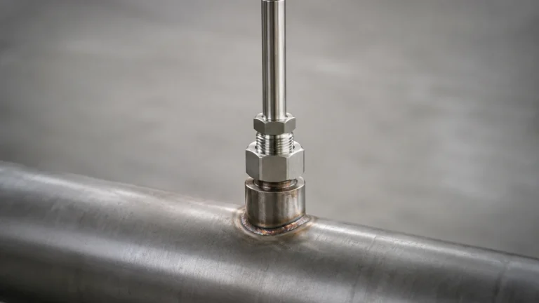
Level Fuel
Level Fuel
Effective management of fuel resources is a cornerstone of operational efficiency in industries ranging from power generation and data centers to logistics and chemical processing. Accurately monitoring the level fuel in storage tanks is not merely a matter of inventory control; it is a critical safety and reliability requirement. Whether managing diesel for emergency backup generators or heavy fuel oil for industrial boilers, engineers must select measurement technologies that can withstand the specific chemical and physical properties of the stored media.
This guide provides a technical overview of the primary methods used to measure level fuel, the engineering criteria for instrument selection, and the practical considerations required for successful installation and long-term maintenance.
Measurement Principles for Fuel Level Detection
To select the appropriate instrument, it is first necessary to understand the physical principles governing different measurement technologies. Fuel, as a medium, presents specific challenges including varying dielectric constants, the potential for vapor accumulation, and flammable atmospheres.
Hydrostatic Pressure Measurement
Hydrostatic level measurement is based on the principle that the pressure at the bottom of a tank is directly proportional to the height of the liquid column above it. The relationship is defined by the formula:
P = ρ × g × h
Where *P* is the pressure, *ρ* (rho) is the density of the fuel, *g* is the gravitational constant, and *h* is the height of the liquid.
In fuel applications, a hydrostatic transmitter is typically submerged at the bottom of the tank or mounted to a flange near the base. Because fuel density can change with temperature, high-precision systems often include temperature compensation to maintain accuracy. These sensors are robust and cost-effective but require contact with the medium.
Ultrasonic (Time-of-Flight)
Ultrasonic sensors are non-contact devices that emit high-frequency sound pulses. These pulses reflect off the surface of the fuel and return to the sensor. The device calculates the distance based on the time it takes for the echo to return.
While effective for many diesel applications, ultrasonic sensors can be affected by the composition of the air space above the fuel. For instance, heavy fuel vapors can change the speed of sound, leading to measurement errors if the sensor does not have advanced compensation algorithms. They are generally best suited for atmospheric tanks with stable temperature conditions.
Radar Level Measurement (FMCW and Pulse)
Radar technology uses electromagnetic waves (microwaves) rather than sound. There are two primary types: Pulse Radar and Frequency Modulated Continuous Wave (FMCW).
* Pulse Radar: Sends a signal and measures the time delay of the return.
* FMCW Radar: Continuously sends a signal with a varying frequency. The difference in frequency between the transmitted and received signal is proportional to the distance.
For level fuel monitoring, radar is often the preferred choice because electromagnetic waves are unaffected by vapors, pressure, or temperature fluctuations in the tank's headspace. Modern 80GHz radar sensors offer narrow beam angles, which allow for installation in tanks with internal obstructions like heating coils or ladders.
Magnetic Level Gauges
Magnetic level gauges are used for side-mounting on tanks. They consist of a bypass chamber containing a float with an internal magnet system. As the fuel level rises or falls, the float moves accordingly, flipping magnetic flaps on an external scale to provide a visual indication. These can be equipped with reed switches or transmitters for remote signal output, providing both a mechanical backup and a digital feed.
Selection Criteria for Level Fuel Applications
Choosing the right technology requires a detailed analysis of the application environment. The following table compares the most common technologies used in fuel measurement:
| Technology | Typical Accuracy | Contact Type | Best For | Limitations |
| :— | :— | :— | :— | :— |
| Radar | ±1 mm to ±3 mm | Non-contact | High-precision, volatile fuels | Higher initial investment |
| Ultrasonic | ±0.25% of range | Non-contact | Standard diesel storage | Affected by heavy vapor/foam |
| Hydrostatic | ±0.1% to ±0.5% | Contact | Vented tanks, deep wells | Sensitive to density changes |
| Magnetic Gauge | ±5 mm (visual) | Contact | High-pressure/temp tanks | Requires side-tank mounting |
| Level Switch | N/A (Point level) | Contact | Overfill protection | No continuous measurement |
Medium Properties
When measuring level fuel, the dielectric constant (εr) is a critical factor for radar sensors. Most fuels have a low dielectric constant (typically between 1.9 and 2.5). This means the reflected signal is weaker than it would be for water. Modern sensors from professional manufacturers like Welk are designed with high sensitivity to reliably track these low-reflectivity surfaces.
Tank Geometry and Environment
The physical shape of the tank (horizontal cylindrical vs. vertical) and the presence of internal structures must be considered. For horizontal tanks, the relationship between level and volume is non-linear, requiring the level meter to have a built-in strapping table or volume conversion capability.
Installation Considerations
Proper installation is as important as selecting the right sensor. Failure to follow engineering best practices can lead to signal loss or false readings.
1. Avoid the Center: In many tanks, the center is prone to the "vortex effect" during filling or emptying. Additionally, the center of a domed tank can act as a parabolic reflector, creating unwanted signal interference.
2. Nozzle Height and Diameter: For radar and ultrasonic sensors, the mounting nozzle should be as short and wide as possible. If the nozzle is too narrow or too long, the signal may reflect off the nozzle walls before reaching the fuel.
3. Stilling Wells: In applications where the fuel surface is turbulent or where there is significant foam, a stilling well (a vertical pipe installed inside the tank) can be used to provide a calm surface for the sensor to measure. This is particularly common when measuring light fuels in large storage tanks.
4. Dead Zones: Every sensor has a "dead zone" or "blocking distance" directly beneath the sensor face where measurement is impossible. Ensure the sensor is mounted high enough that the maximum expected fuel level does not enter this zone.
Limitations and Risks
While modern instrumentation is highly reliable, engineers must be aware of specific limitations when monitoring level fuel:
* Vapor and Condensation: In closed tanks, fuel can evaporate and condense on the sensor face. While radar is largely immune to the vapor itself, heavy condensation on the antenna can attenuate the signal. Choosing a sensor with a PTFE or specialized drip-off antenna design can mitigate this.
* Temperature Stratification: In large outdoor tanks, fuel density may not be uniform if the tank is partially heated or exposed to direct sunlight. This can affect hydrostatic sensors that rely on a constant density for height calculation.
* Hazardous Areas: Fuel storage environments are often classified as hazardous (Ex/ATEX). All level measurement equipment must carry the appropriate certifications for the specific zone (e.g., Zone 0, 1, or 2) to prevent ignition risks.
Frequently Asked Questions (FAQ)
Q: Can I use the same sensor for diesel and heavy fuel oil?
A: While the technology (like radar) might be the same, the configuration may differ. Heavy fuel oils often require heating to remain fluid, which increases the operating temperature and potential for coating on the sensor. A non-contact radar is generally better for heavy oils than a contact-based hydrostatic sensor which might clog.
Q: How do I handle volume calculations in a horizontal tank?
A: Most digital level transmitters allow you to input a tank strapping table. You provide a series of points (e.g., 100mm = 500 liters) and the device uses linear interpolation to provide an accurate volume output.
Q: Is it necessary to have a separate overfill alarm?
A: Yes. For safety and regulatory compliance, it is standard practice to use a continuous level transmitter for inventory and a separate, independent high-level switch (such as a tuning fork or float switch) for emergency overfill protection.
Conclusion
Selecting the right instrument for monitoring level fuel involves balancing accuracy requirements, tank conditions, and budget. While hydrostatic and ultrasonic sensors offer cost-effective solutions for many standard applications, radar technology has become the industry standard for high-accuracy, low-maintenance fuel measurement due to its immunity to environmental variables.
For engineers and procurement professionals looking to optimize their fuel management systems, it is essential to partner with a manufacturer that provides a range of technologies and customization options. For a comprehensive overview of available technologies and technical specifications, professionals can visit the Main Page to review product options and application support.