Municipal Water Tanker
Municipal Water Tanker
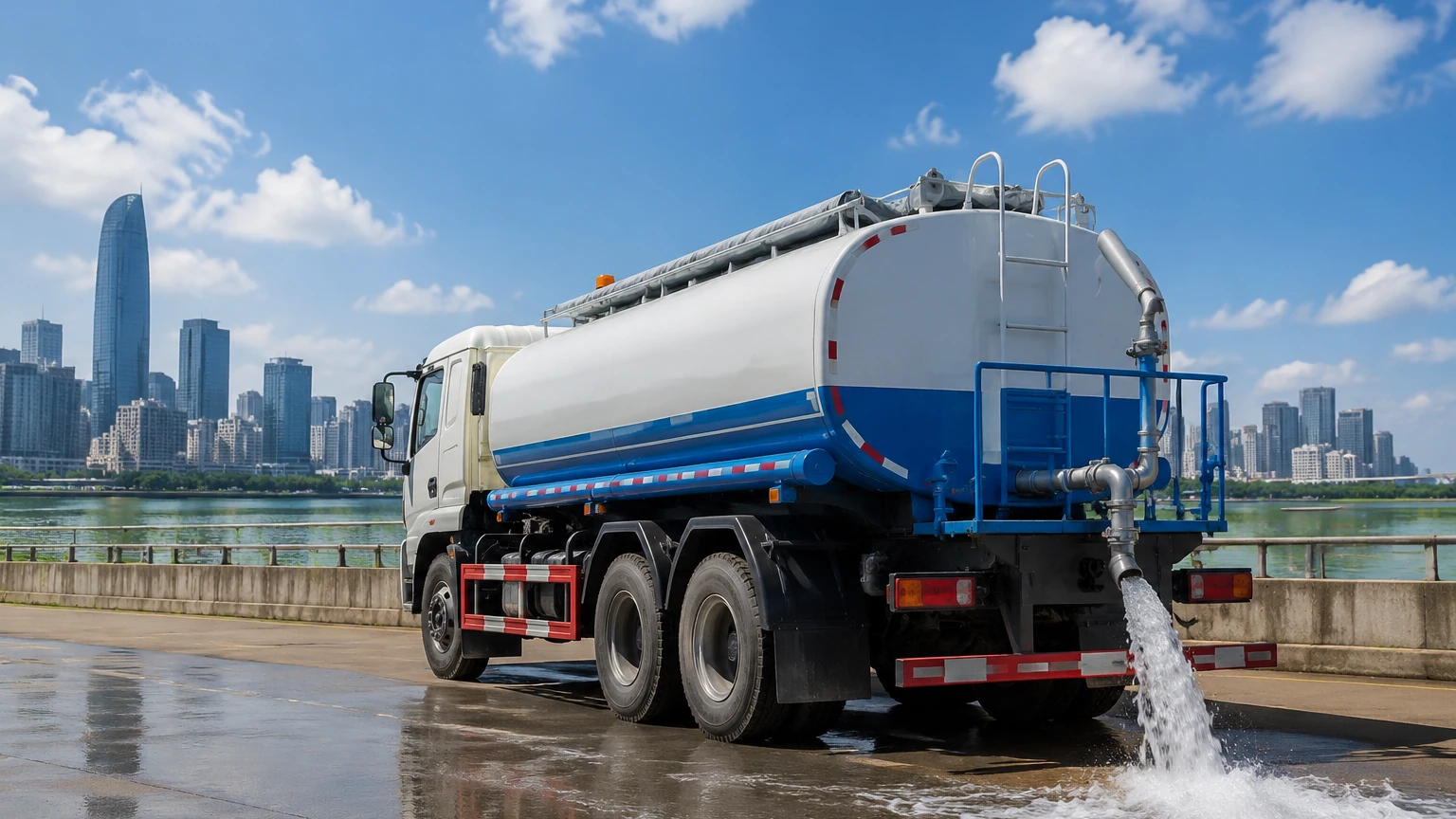
In the realm of urban infrastructure and public works, the municipal water tanker serves as a critical mobile asset. Whether deployed for emergency potable water distribution, dust suppression at construction sites, or the maintenance of public green spaces, these vehicles require precise liquid level monitoring to ensure operational efficiency. For fleet managers and municipal engineers, selecting the correct level measurement technology is not merely a matter of convenience; it is essential for preventing pump cavitation, optimizing delivery routes, and maintaining the integrity of the water supply.
Accurate level measurement within a municipal water tanker allows for real-time inventory tracking and ensures that the vehicle operates within safe weight limits. This article explores the technical principles of level measurement suitable for mobile water applications and provides a framework for selecting the most appropriate instrumentation.
Measurement Principles for Tanker Applications
Before selecting a specific sensor for a municipal water tanker, it is necessary to understand the underlying physical principles of the most common measurement technologies. Each method has distinct advantages depending on the tank's geometry and the environmental conditions of the application.
Hydrostatic Pressure Measurement
Hydrostatic level transmitters operate on the principle that the pressure at the bottom of a liquid column is directly proportional to the height of that column. The formula used is $P = \rho \cdot g \cdot h$, where $P$ is pressure, $\rho$ is the density of the liquid, $g$ is the gravitational constant, and $h$ is the height of the liquid.
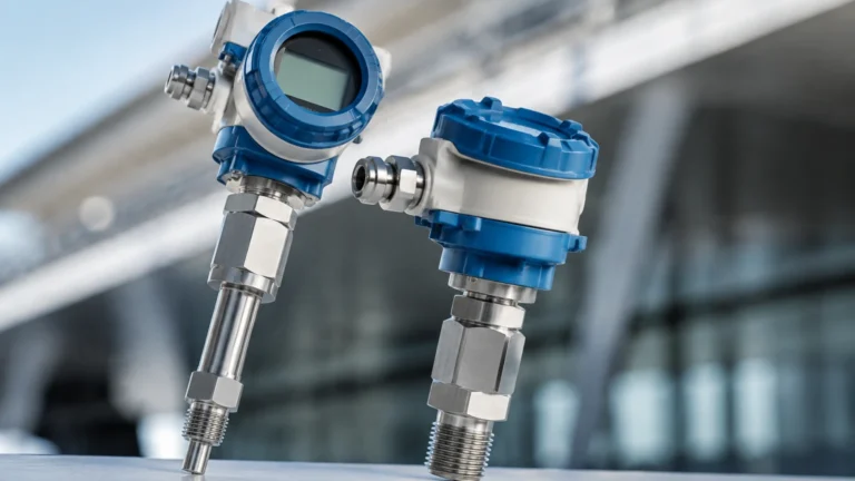
In a municipal water tanker, a submersible pressure transducer or a flange-mounted sensor at the bottom of the tank measures the head pressure. This value is then converted into a level reading. Since water density is relatively constant, this method is highly reliable, provided the sensor can account for atmospheric pressure changes (usually via a vented cable).
Ultrasonic (Non-Contact) Measurement
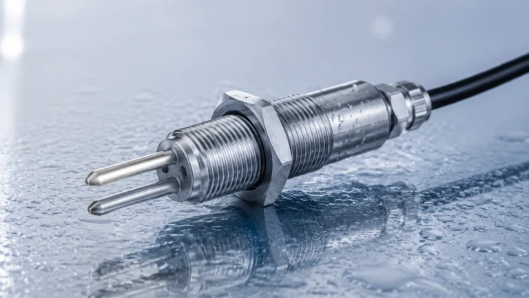
Ultrasonic sensors emit high-frequency sound pulses that travel through the air, reflect off the water surface, and return to the transducer. The sensor measures the "time-of-flight" of the pulse. By knowing the speed of sound in air, the distance to the liquid surface is calculated.
For a municipal water tanker, ultrasonic technology is often preferred because it is non-contact. This reduces the risk of contaminating potable water and prevents sensor wear from moving parts. However, the speed of sound is affected by air temperature, requiring sensors with integrated temperature compensation to maintain accuracy.
Radar (FMCW) Measurement
Radar level meters, particularly those using Frequency Modulated Continuous Wave (FMCW) technology, emit microwave signals. Similar to ultrasonic sensors, they measure the time-of-flight. However, microwaves are unaffected by air temperature, pressure, or vapor. Radar provides the highest precision and is particularly effective in tankers where turbulence or condensation might interfere with ultrasonic signals.
Magnetic Level Gauges
Magnetic level gauges utilize a float containing an internal magnet that moves with the liquid level inside a bypass chamber or directly within the tank. As the float moves, it flips magnetic flags on an external scale, providing a visual indication. For electronic integration, a magnetostrictive transmitter can be added to provide a 4-20mA signal to the vehicle's telemetry system.
Selection Criteria for Municipal Water Tankers
Choosing the right instrument for a municipal water tanker involves evaluating several technical factors unique to mobile liquid transport.
1. Tank Geometry and Baffles: Most municipal water tankers are equipped with internal baffles to prevent liquid sloshing during transport. These baffles can create physical obstructions for radar or ultrasonic beams. Sensors must be positioned in a location that provides a clear "view" of the liquid surface or be programmed to ignore false echoes from internal structures.
2. Vibration and Mechanical Stress: Unlike stationary industrial tanks, a tanker is subject to constant vibration and mechanical shocks. The mounting hardware and the internal electronics of the level meter must be rated for high-vibration environments to prevent premature failure.
3. Media Purity: If the tanker is used for drinking water (potable water), all wetted parts of the sensor must comply with local health and safety regulations (such as NSF/ANSI standards). Stainless steel 316L or food-grade plastics are standard requirements.
4. Power Supply: Instruments on a municipal water tanker typically run on 12V or 24V DC power provided by the vehicle's electrical system. Low power consumption is vital to avoid draining the vehicle's battery during stationary periods.
Practical Selection Table
The following table compares the most common level measurement technologies for use in a municipal water tanker environment.
| Technology | Accuracy | Contact Type | Best Use Case | Limitations |
| :— | :— | :— | :— | :— |
| Hydrostatic | ±0.25% to 0.5% | Contact | Deep tanks, budget-sensitive projects | Sensitive to changes in liquid density |
| Ultrasonic | ±0.25% of range | Non-contact | Potable water, standard tankers | Affected by heavy foam or extreme steam |
| Radar (80GHz) | ±1 mm to 2 mm | Non-contact | High-precision, turbulent tanks | Higher initial investment cost |
| Magnetic Gauge | ±5 mm (visual) | Contact | Visual backup for operators | Moving parts can wear over time |
For engineers looking to integrate these technologies into a broader fleet management system, it is helpful to Review product options and application support to ensure compatibility with existing telemetry hardware.
Installation Considerations and Engineering Best Practices
Proper installation is as critical as sensor selection. In a municipal water tanker, the following practices should be observed:
* Dead Zone Management: Every non-contact sensor (ultrasonic and radar) has a "dead zone" or "blocking distance" near the transducer face where measurements cannot be taken. The sensor should be mounted high enough—often using a nozzle or standpipe—to ensure the tank can be filled to its maximum capacity without entering the dead zone.
* Slosh Suppression: To prevent erratic readings while the vehicle is in motion, signal damping should be configured in the transmitter's software. This averages the level over several seconds to provide a stable output despite the movement of the water.
* Mounting Location: Avoid mounting sensors directly above the fill inlet. The turbulence and aeration caused during the filling process will result in inaccurate readings or signal loss.
* Grounding: Ensure the instrument is properly grounded to the vehicle chassis to prevent electrical interference from the alternator or other onboard electronics.
Limitations and Challenges
While modern instrumentation is highly advanced, certain limitations remain when monitoring a municipal water tanker.
Environmental Factors: In extremely cold climates, ice formation on the surface of the water or the sensor face can impede ultrasonic and radar signals. Hydrostatic sensors are less affected by surface ice but can be damaged if the water freezes solid around the diaphragm.
Tank Material: While most municipal tankers are steel or aluminum, some are fiberglass (FRP) or plastic. Radar signals can pass through plastic, which may require specific calibration to ensure the sensor does not pick up reflections from the ground beneath the vehicle if the tank is nearly empty.
Maintenance Requirements: Even "maintenance-free" non-contact sensors require occasional inspection. In a municipal water tanker, minerals from hard water can build up on the sensor face, potentially weakening the signal over time. A simple wipe-down during scheduled vehicle maintenance is usually sufficient.
Frequently Asked Questions (FAQs)
Q: Can I use a standard industrial level sensor on a water tanker?
A: Yes, but you must ensure it is rated for the vibration levels of a mobile application and that the electrical output (e.g., 4-20mA or Modbus) is compatible with the vehicle’s tracking system.
Q: How do I handle the "sloshing" effect when the truck is moving?
A: Most professional-grade level meters allow for "output damping." By increasing the damping time (e.g., to 10 or 20 seconds), the sensor will average the peaks and troughs of the waves to provide a steady reading.
Q: Is radar better than ultrasonic for water tankers?
A: Radar is generally more robust because it is unaffected by temperature changes and vapor. However, for many standard municipal applications, ultrasonic sensors provide a more cost-effective solution that is perfectly adequate for water.
Q: What is the best way to monitor the level remotely?
A: The level meter should be connected to a GPS/Telematics unit. The 4-20mA signal from the sensor is converted into a digital value and transmitted via cellular or satellite networks to a central municipal dashboard.
Conclusion
Effective management of a municipal water tanker fleet relies on the data provided by reliable level measurement instruments. By understanding the principles of hydrostatic, ultrasonic, and radar technologies, municipal engineers can specify the right tool for their specific environmental and operational needs. Proper installation, focusing on baffle avoidance and slosh suppression, ensures that the data remains actionable, helping municipalities conserve water, reduce fuel costs, and serve their communities more effectively.