Liquid Flow Controller
Liquid Flow Controller
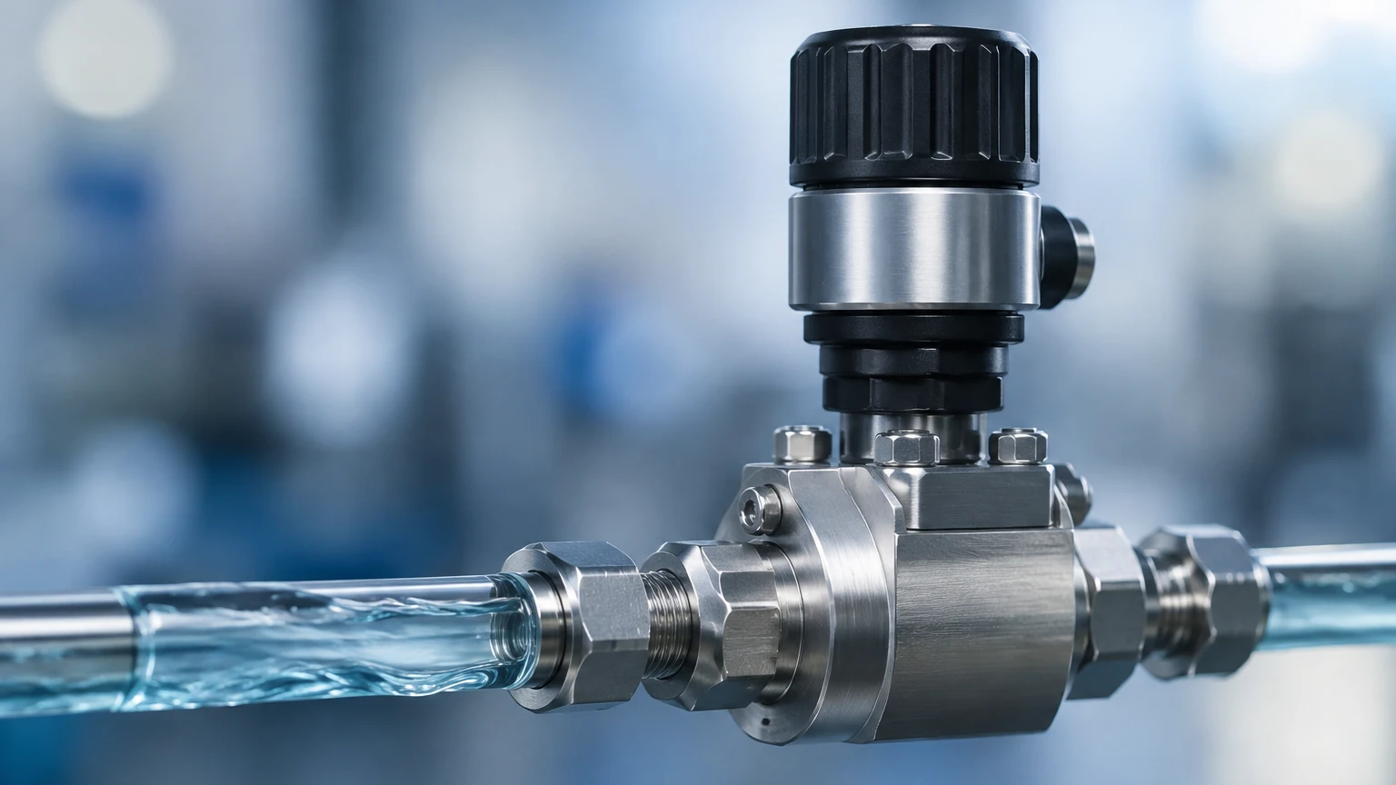
In industrial process automation, the ability to precisely manage the movement of fluids is fundamental to product quality, safety, and operational efficiency. A liquid flow controller (LFC) is an integrated system designed to measure the flow rate of a liquid and automatically adjust a control element—typically a valve or a pump—to maintain a specific setpoint. Unlike a simple flow meter, which only provides data, a controller actively intervenes in the process to ensure that the actual flow matches the desired parameters.
For engineers and plant managers, selecting the correct liquid flow controller requires a deep understanding of fluid dynamics, sensor technology, and control theory. This guide examines the technical principles, selection criteria, and integration strategies necessary for implementing effective flow control in B2B industrial environments.
Core Principles of Liquid Flow Control
A liquid flow controller operates on a closed-loop feedback principle. The system generally consists of three primary components: a flow sensor, a PID (Proportional-Integral-Derivative) controller, and an actuator.
The Feedback Loop
1. Sensing: The flow sensor continuously monitors the volume or mass of liquid passing through the line per unit of time (e.g., liters per minute or kilograms per hour).
2. Comparison: The sensor sends an electronic signal (often 4-20mA, 0-10V, or a digital protocol like Modbus) to the controller. The controller compares this "Process Variable" (PV) against the user-defined "Setpoint" (SP).
3. Correction: If a discrepancy exists, the controller calculates the necessary adjustment and sends a signal to the actuator (a control valve or a variable frequency drive on a pump) to increase or decrease the flow.
Measurement Technologies
Before a controller can act, it must accurately measure the flow. Several physical principles are commonly employed:
* Thermal Mass Flow: This method measures the heat dissipation from a heated surface into the flowing liquid. It is highly accurate for low flow rates and provides direct mass flow measurement without requiring temperature or pressure compensation.
* Differential Pressure (DP): By placing an orifice plate or Venturi tube in the flow path, a pressure drop is created. The square root of the pressure difference between the upstream and downstream sides is proportional to the flow rate.
* Coriolis Force: This technology measures the inertia caused by liquid flowing through vibrating tubes. It is considered the gold standard for accuracy as it measures true mass flow, density, and temperature simultaneously.
* Ultrasonic (Transit-Time): Ultrasonic pulses are sent upstream and downstream. The difference in travel time is used to calculate the velocity. This is a non-invasive method ideal for high-purity or corrosive liquids.
Comparison of Flow Measurement Technologies
Choosing the right technology depends on the fluid's properties and the required precision. The following table provides a general comparison of common industrial methods used within liquid flow controller systems.
| Technology | Typical Accuracy | Fluid Suitability | Primary Advantage |
| :— | :— | :— | :— |
| Thermal Mass | ±1.0% of FS | Clean, non-viscous | Excellent low-flow sensitivity |
| Coriolis | ±0.1% to 0.2% | Most liquids/slurries | Direct mass measurement; very high accuracy |
| Differential Pressure | ±1.0% to 2.0% | Gas and clean liquids | Robust, well-understood technology |
| Ultrasonic | ±0.5% to 1.0% | Clean or slightly dirty | Non-invasive; no pressure drop |
| Electromagnetic | ±0.2% to 0.5% | Conductive liquids | No moving parts; handles slurries well |
Selection Criteria for Industrial Applications
When specifying a liquid flow controller, engineers must look beyond the basic flow rate. Several secondary factors can significantly impact the longevity and reliability of the device.
1. Chemical Compatibility
The wetted materials of the controller must be resistant to the process fluid. While 316L stainless steel is standard, highly corrosive chemicals like hydrochloric acid or sodium hypochlorite may require PTFE (Teflon), Hastelloy, or ceramic components.
2. Viscosity and Density
Changes in viscosity can affect the Reynolds number of the flow, which in turn impacts the accuracy of DP and some ultrasonic meters. Coriolis controllers are generally the most resilient to changes in viscosity. If the liquid is non-Newtonian, specialized calibration is often required.
3. Turndown Ratio
The turndown ratio (or rangeability) defines the range over which the controller can maintain its specified accuracy. For example, a controller with a maximum flow of 100 L/min and a 50:1 turndown ratio can accurately control flow down to 2 L/min. Applications requiring wide variations in flow need high turndown capabilities.
4. Response Time
In fast-paced bottling lines or chemical injection systems, the speed at which the controller can reach the setpoint is critical. Thermal mass controllers may have slower response times (seconds) compared to fast-acting Coriolis or electromagnetic systems (milliseconds).
Integrating Flow Control with Level Measurement Systems
In many industrial processes, flow control and level measurement are two sides of the same coin. While a liquid flow controller manages the rate of transfer, level sensors provide the ultimate verification of the volume within a vessel. For example, in a tank filling application, the flow controller ensures the liquid enters at a steady rate to prevent splashing or foaming, while a radar or ultrasonic level meter ensures the tank does not overflow.
Integrating these two data points allows for mass balance calculations, which are essential for leak detection and inventory management. If the flow controller indicates that 1,000 liters have been pumped into a tank, but the level transmitter shows an increase equivalent to only 950 liters, operators can quickly identify a potential leak or a calibration error in the instruments. For high-quality instrumentation that supports these integrated architectures, engineers often consult the Main Page to review product options and application support for radar, ultrasonic, and hydrostatic level transmitters.
Installation Considerations and Engineering Best Practices
Even the most advanced liquid flow controller will fail to perform if installed incorrectly. Proper mechanical and electrical installation is paramount to achieving the rated accuracy.
Piping and Straight Runs
Most flow sensors require a "fully developed flow profile" to measure accurately. Turbulence caused by elbows, valves, or pumps can introduce significant errors. A common rule of thumb is to provide at least 10 pipe diameters (10D) of straight, unobstructed pipe upstream and 5 diameters (5D) downstream of the controller. If space is limited, flow conditioners or vanes may be necessary.
Orientation and Entrapped Air
For liquid applications, the controller should ideally be installed in a vertical pipe section with the flow moving upward. This ensures the pipe is always full and prevents air bubbles from being trapped in the sensor. If horizontal installation is necessary, the sensor should not be placed at the highest point of the piping system, as air pockets will collect there and cause signal dropouts or erratic readings.
Electrical Noise and Grounding
Industrial environments are often rife with electromagnetic interference (EMI) from large motors and variable frequency drives (VFDs). Using shielded cables and ensuring a common ground between the flow controller and the pipe (especially for electromagnetic flow meters) is essential to prevent signal drift.
Operational Limitations and Risk Mitigation
Understanding the boundaries of liquid flow controller technology helps in preventing premature failure and process downtime.
* Cavitation: If the pressure drop across the control valve is too high, the liquid may vaporize and then rapidly collapse. This phenomenon, known as cavitation, can erode valve seats and sensor internals within days. Proper sizing and the use of anti-cavitation trim are required.
* Scaling and Fouling: In water treatment or mining applications, mineral deposits (scaling) or biological growth (fouling) can coat the sensor electrodes or change the internal diameter of the pipe. This leads to a gradual drift in accuracy. Regular CIP (Clean-In-Place) cycles or the selection of non-contact ultrasonic sensors can mitigate this risk.
* Zero Drift: Over time, electronic components can experience "zero drift," where the controller indicates a small flow even when the valve is fully closed. Periodic "zeroing" of the instrument under no-flow conditions is a standard maintenance requirement.
Frequently Asked Questions (FAQ)
Q: Can a liquid flow controller handle slurries or liquids with solids?
A: Yes, but technology choice is limited. Electromagnetic flow controllers are ideal for conductive slurries because they have no moving parts or obstructions. Coriolis meters can also handle solids but may suffer from abrasive wear over time.
Q: What is the difference between a flow meter and a flow controller?
A: A flow meter only measures and displays the flow rate. A flow controller includes the logic (PID) and the physical means (valve/pump interface) to change the flow rate to match a specific target.
Q: How often should a liquid flow controller be calibrated?
A: For most industrial applications, annual calibration is recommended. However, in highly regulated industries like pharmaceuticals or food and beverage, semi-annual or even quarterly calibration may be required to ensure compliance with safety standards.
Q: Does pressure affect the accuracy of a liquid flow controller?
A: Liquids are generally incompressible, so pressure changes have a negligible effect on volumetric flow. However, high pressure can affect the mechanical integrity of the sensor housing, and extreme pressure drops can lead to the aforementioned cavitation issues.
Q: Can I use a liquid flow controller for gases?
A: While the physical principles (like thermal mass or DP) can be similar, the hardware and calibration for a liquid flow controller are specifically optimized for the density and viscosity of liquids. Using a liquid-calibrated unit for gas will result in significant errors and potential hardware damage.
By carefully considering the fluid properties, installation environment, and the synergy between flow and level measurement, B2B stakeholders can implement liquid flow control solutions that enhance process stability and reduce long-term operational costs.