Fuel Level Sensing
Fuel Level Sensing
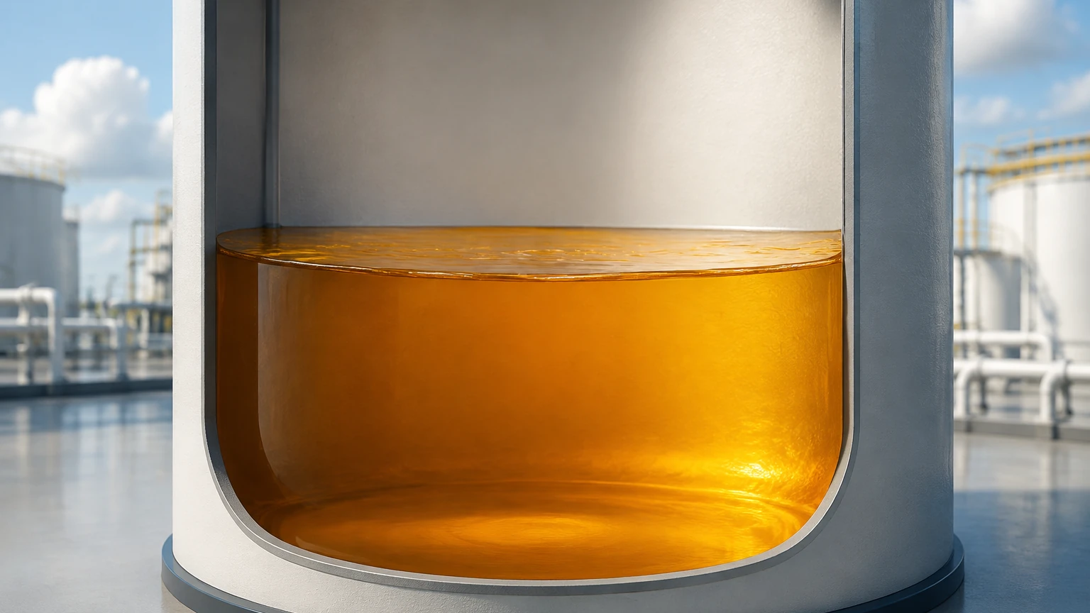
Fuel level sensing is a critical requirement in industrial automation, power generation, and chemical processing. Accurate measurement of fuels—ranging from diesel and gasoline to heavy fuel oils and biofuels—ensures operational continuity, prevents environmental hazards from overfills, and facilitates precise inventory management. In professional engineering contexts, selecting the appropriate fuel level sensing technology requires an understanding of fluid dynamics, dielectric properties, and the physical constraints of the storage vessel.
Measurement Principles of Fuel Level Sensors
Before selecting a specific instrument, engineers must evaluate the underlying physical principles used to detect the liquid-air interface. The most common technologies employed in industrial fuel level sensing include radar, ultrasonic, hydrostatic pressure, and magnetic displacement.
1. Radar Level Measurement (Non-Contact)
Radar level meters operate on the Time-of-Flight (ToF) principle. The sensor emits high-frequency microwave pulses (typically in the 26 GHz or 80 GHz range) that travel at the speed of light. When these pulses hit the fuel surface, they are reflected back to the sensor. The distance is calculated based on the time interval between emission and reception.
Because radar waves do not require a medium for propagation, they are unaffected by temperature fluctuations, vacuum conditions, or high pressure. In fuel applications, the dielectric constant (εr) of the fuel is a key factor; fuels typically have low dielectric constants (e.g., diesel is approximately 2.1), which requires high-sensitivity radar sensors to ensure a strong return signal.
2. Ultrasonic Level Measurement
Similar to radar, ultrasonic sensors use the ToF principle but utilize sound waves instead of electromagnetic waves. The transducer emits an ultrasonic pulse that reflects off the fuel surface. The speed of sound is dependent on the air temperature and composition within the tank's headspace. While cost-effective, ultrasonic sensors can be sensitive to heavy fuel vapors or significant temperature gradients, which can alter the speed of sound and introduce measurement errors.
3. Hydrostatic Pressure Measurement
Hydrostatic level transmitters measure the pressure exerted by the liquid column. The principle is based on the formula: $P = \rho \cdot g \cdot h$, where $P$ is pressure, $\rho$ is the density of the fuel, $g$ is gravity, and $h$ is the height of the liquid. For fuel sensing, these sensors are often submersible or mounted at the bottom of the tank. This method is highly reliable but requires the fuel density to remain constant. If the fuel type or temperature changes significantly, the density shift will result in an inaccurate level reading unless compensated for by the control system.
4. Magnetic Level Gauges
Magnetic level gauges consist of a float containing a permanent magnet that moves with the fuel level inside a bypass chamber or directly in the tank. As the float rises or falls, it flips magnetic flaps or interacts with a reed-switch array or magnetostrictive sensor. This provides both a local visual indication and a remote electronic signal. This technology is particularly useful for high-pressure fuel storage where a physical visual reference is required alongside electronic monitoring.
Practical Selection Criteria for Fuel Level Sensing
Choosing the right sensor involves more than just selecting a measurement principle. Engineers must consider the chemical and physical environment of the application. The following table provides a comparison of technologies based on typical industrial requirements.
| Feature | Radar (80 GHz) | Ultrasonic | Hydrostatic | Magnetic Gauge |
| :— | :— | :— | :— | :— |
| Accuracy | ±1 mm to ±2 mm | ±0.25% of range | ±0.1% to ±0.5% | ±5 mm |
| Measurement Range | Up to 30m (standard) | 0.5m to 15m | Up to 200m H2O | Up to 6m (standard) |
| Vapor Sensitivity | None | High | None | None |
| Media Contact | Non-contact | Non-contact | Contact | Contact |
| Cost | High | Low to Medium | Medium | Medium to High |
| Maintenance | Very Low | Low | Moderate | Moderate |
When evaluating these options, the primary consideration is often the presence of vapors. Fuels are volatile; gasoline, in particular, creates a dense vapor layer that can attenuate ultrasonic signals. In such cases, radar or hydrostatic sensors are preferred. For more information on specific instrument specifications, you can Review product options and application support to match a sensor to your specific fuel type.
Installation Considerations
Proper installation is as important as technology selection. An incorrectly mounted sensor will provide erratic data regardless of its inherent accuracy.
1. Dead Zones (Blocking Distance): All top-mounted sensors (radar and ultrasonic) have a "dead zone" directly beneath the transducer where measurement is impossible. For a sensor with a 200 mm (approx. 7.87 inches) dead zone, the tank must never be filled above this point, or the sensor will lose its signal.
2. Internal Obstructions: Fuel tanks often contain internal structures such as heating coils, ladders, or agitators. Radar and ultrasonic beams spread as they travel (the beam angle). If the beam hits an obstruction, it creates a "false echo." Modern sensors allow for "false echo suppression" mapping, but it is best to mount the sensor at least 300 mm to 500 mm away from the tank wall and any internal obstacles.
3. Nozzle Height and Diameter: The mounting nozzle should be as short as possible. A long, narrow nozzle can cause signal interference (ringing) that masks the true fuel level, especially when the tank is nearly full.
4. Turbulence and Foam: If fuel is being pumped into the tank at high velocity, surface turbulence or foam may occur. Foam can absorb ultrasonic and radar signals. In these environments, using a stilling well (a vertical pipe that stabilizes the liquid surface) is recommended to ensure a clean reflection.
Limitations and Common Risks
In the context of fuel level sensing, several environmental and physical factors can compromise system integrity:
* Thermal Expansion: Fuels have a high coefficient of thermal expansion. A volume of 1,000 liters (approx. 264 gallons) of diesel at 15°C will occupy a different volume at 40°C. If the goal is mass balance or inventory accounting, level sensors must be paired with temperature probes to calculate temperature-compensated volumes.
* Condensation: In outdoor fuel tanks, temperature shifts between day and night cause moisture to condense on the sensor face. While radar is generally resistant, heavy water droplets on an ultrasonic transducer can block the signal. Sensors with PTFE-coated faces or specialized drip-off designs are preferred for these conditions.
* Build-up and Coating: Heavy fuel oils (HFO) are viscous and can coat contact-based sensors like hydrostatic diaphragms or magnetic floats. This coating can increase the weight of a float or dampen a diaphragm, leading to significant drift. Non-contact radar is the standard solution for viscous fuels.
* Hazardous Area Requirements: Most fuels are flammable. Sensors must be rated for hazardous locations (e.g., ATEX, IECEx, or Class I, Div 1). This includes the use of intrinsically safe (IS) barriers or explosion-proof (XP) housings.
Frequently Asked Questions (FAQ)
Q: Can I use an ultrasonic sensor for gasoline level measurement?
A: It is generally not recommended. Gasoline produces heavy vapors that change the density of the air in the tank's headspace. Since the speed of sound varies with air density, the ultrasonic reading will drift significantly. Radar is a much more reliable choice for gasoline.
Q: How does the dielectric constant affect radar sensing in fuel?
A: Radar waves reflect off the surface because of the change in dielectric constant between air (εr ≈ 1) and the fuel. Fuels like diesel (εr ≈ 2.1) are poor reflectors compared to water (εr ≈ 80). Therefore, the radar sensor must have high sensitivity and a high signal-to-noise ratio to accurately track the fuel surface.
Q: Is hydrostatic pressure sensing suitable for vented or pressurized tanks?
A: Hydrostatic sensors measure the pressure relative to the atmosphere. In a vented tank, a standard gauge pressure sensor works well. However, in a pressurized tank, you must use a differential pressure (DP) transmitter to subtract the headspace pressure from the total bottom pressure to isolate the liquid level.
Q: What is the benefit of an 80 GHz radar over a 26 GHz radar for fuel?
A: 80 GHz radar has a much narrower beam angle (often as small as 3 degrees). This makes it easier to install in tanks with internal obstructions or narrow nozzles, as the beam is less likely to hit the tank walls or internal hardware.
Engineering Summary
Effective fuel level sensing requires a balance between accuracy, reliability, and cost. For standard diesel storage, hydrostatic transmitters offer a robust and economical solution, provided the density remains stable. For volatile fuels or tanks with complex internal geometries, non-contact radar (specifically high-frequency 80 GHz models) provides the highest precision and lowest maintenance requirements.
When designing a fuel monitoring system, engineers should prioritize hazardous area certifications and consider the long-term effects of vapor and temperature on the chosen technology. By following proper installation guidelines—such as respecting dead zones and avoiding internal obstructions—the longevity and accuracy of the fuel level sensing system can be ensured. For a comprehensive range of industrial instruments tailored to these applications, visiting the Main Page of a specialized manufacturer can provide the technical documentation necessary for final project specification.