Water Pump with Level Sensor
Water Pump with Level Sensor
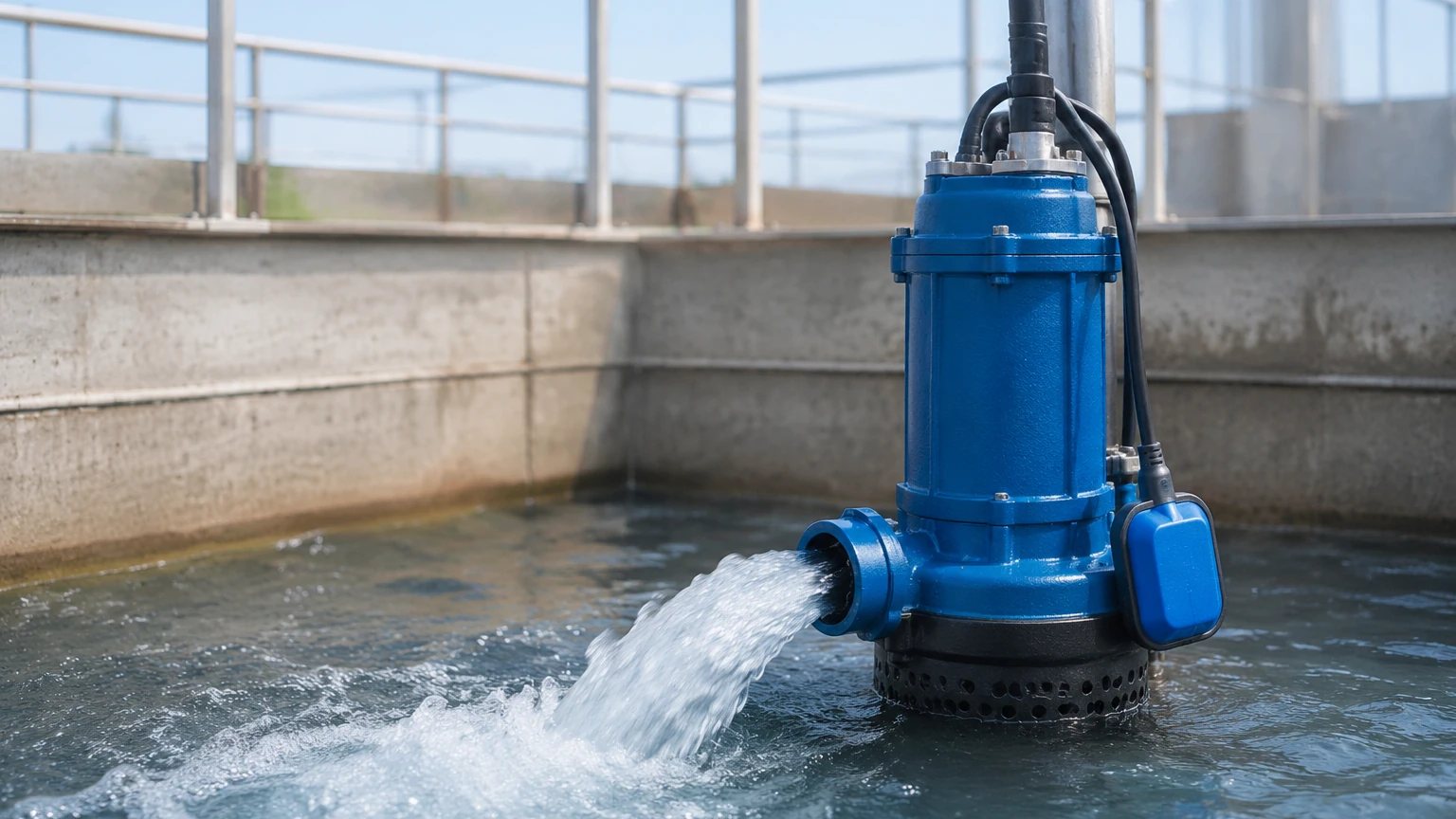
In industrial and municipal water management, the integration of a water pump with level sensor technology is fundamental to operational automation, equipment protection, and resource efficiency. A pump operating without feedback regarding the liquid level is susceptible to dry-running—a leading cause of mechanical seal failure and motor burnout—or overflow conditions that result in environmental hazards and material loss.
By utilizing precise level measurement instruments, engineers can transform a simple fluid transfer process into a sophisticated, self-regulating system. This guide explores the measurement principles, selection criteria, and installation best practices for integrating level sensors with pumping systems.
Measurement Principles in Pump Control
Before selecting a specific sensor for a water pump application, it is essential to understand the underlying physical principles used to detect liquid levels. Each technology offers distinct advantages based on the characteristics of the fluid and the vessel environment.
1. Hydrostatic Pressure Measurement
Hydrostatic level transmitters operate on the principle that the pressure at a specific point in a static liquid is proportional to the height of the liquid column above it. The relationship is defined by the formula: $P = \rho \cdot g \cdot h$, where $P$ is pressure, $\rho$ is the density of the fluid, $g$ is gravity, and $h$ is the height.
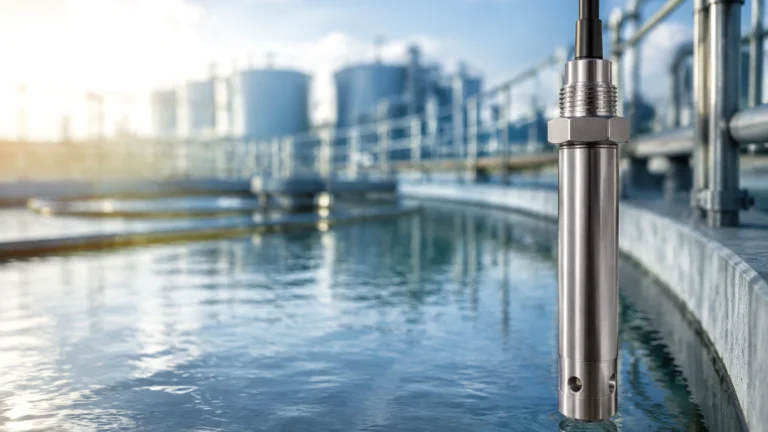
In pump applications, a submersible pressure transducer is lowered to the bottom of the tank or well. It measures the weight of the water above it and converts this into a 4-20mA signal. This method is highly effective for deep wells and large reservoirs because it is unaffected by surface foam or turbulence.
2. Ultrasonic (Non-Contact)
Ultrasonic sensors emit high-frequency sound pulses that reflect off the liquid surface and return to the transducer. The sensor calculates the distance based on the time-of-flight of the sound wave. Because these sensors do not touch the liquid, they are ideal for wastewater or corrosive chemicals that might degrade contact-based probes. However, they can be affected by heavy steam, foam, or significant temperature fluctuations which alter the speed of sound.
3. Radar (Microwave) Technology
Similar to ultrasonic sensors, radar level meters use time-of-flight but employ electromagnetic waves (microwaves) rather than sound. Radar is immune to air temperature changes, vacuum conditions, and high pressure. For industrial water pumps handling volatile or high-temperature fluids, radar provides the highest level of accuracy and reliability.
4. Float and Conductivity Switches
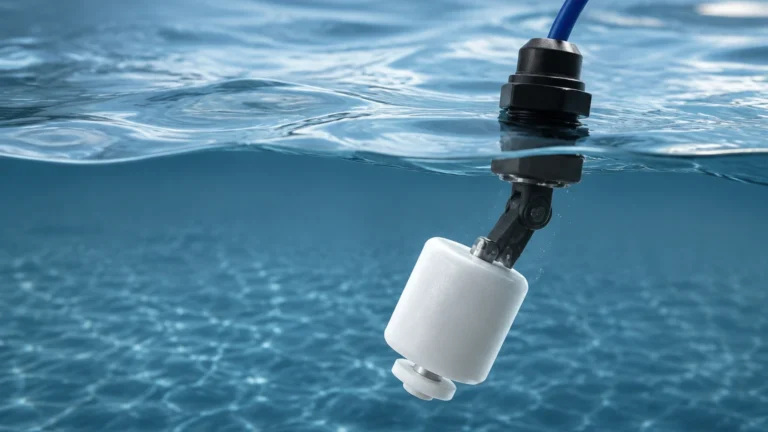
These are point-level detection methods. A float switch uses a buoyant body containing a microswitch or magnet that triggers when the water reaches a specific height. Conductivity probes rely on the electrical conductivity of the water to bridge the gap between two electrodes. These are typically used for simple start/stop logic rather than continuous monitoring.
Selection Criteria for Water Pump Level Control
Selecting the right water pump with level sensor configuration requires an evaluation of the operating environment and the required precision. The following table provides a comparison of common technologies used in B2B industrial applications.
| Technology | Accuracy | Ideal Application | Limitations | Maintenance Level |
| :— | :— | :— | :— | :— |
| Hydrostatic | High (±0.1% to 0.5%) | Deep wells, vented tanks, reservoirs | Sensitive to density changes | Low (Submersible) |
| Ultrasonic | Moderate (±0.25%) | Open channels, wastewater pits | Affected by foam and steam | Low (Non-contact) |
| Radar | Excellent (±1mm to 3mm) | Chemical storage, high-pressure tanks | Higher initial cost | Very Low |
| Float Switch | Low (Point only) | Sump pumps, basic bilge control | Moving parts can clog | Moderate |
| Capacitance | High | Small tanks, non-conductive fluids | Requires calibration for fluid | Moderate |
When evaluating these options, engineers should consult the Main Page of professional instrumentation manufacturers to ensure the chosen device meets the specific chemical compatibility and pressure ratings of the project.
System Integration and Automation Logic
The integration of a level sensor with a water pump typically follows one of two logic structures: Point-Level Control or Continuous Level Management.
Point-Level Control (Discrete)
In this setup, two or more sensors (or a multi-point float) are used.
- High Level (Start): When the water reaches the upper threshold, the sensor closes a relay, starting the pump to drain the tank.
- Low Level (Stop): Once the water drops to the minimum safe level, the sensor opens the circuit, stopping the pump to prevent dry-running.
Continuous Level Management (Analog/Digital)
Using a 4-20mA or RS485 Modbus signal from a radar or hydrostatic transmitter, a Programmable Logic Controller (PLC) or Variable Frequency Drive (VFD) manages the pump. This allows for "proportional control," where the pump speed increases as the level rises, maintaining a steady state rather than constant cycling. This reduces mechanical wear on the pump motor and saves energy.
Installation Considerations and Best Practices
Proper installation is as critical as sensor selection. Even the most advanced radar level meter will fail if placed incorrectly.
1. Avoid Turbulence: Do not install sensors directly above the pump inlet or the tank's fill pipe. Turbulence and bubbles can cause erratic readings in ultrasonic and hydrostatic sensors. If turbulence is unavoidable, use a stilling well (a perforated pipe) to provide a calm area for measurement.
2. Dead Zones (Blocking Distance): Ultrasonic and radar sensors have a "dead zone" near the transducer face (typically 10cm to 50cm). Ensure the maximum water level never enters this zone, or the sensor will lose track of the surface.
3. Cable Protection: For submersible hydrostatic sensors, the cable often contains a vent tube to compensate for atmospheric pressure. This tube must remain unobstructed and dry. Use a junction box with a desiccant filter in high-humidity environments.
4. Mounting Orientation: Ensure non-contact sensors are mounted perfectly perpendicular to the liquid surface. A tilt of even a few degrees can cause the signal to bounce away from the receiver, leading to signal loss.
Limitations and Environmental Factors
While a water pump with level sensor system adds significant value, users must be aware of technical limitations:
- Fluid Density: Hydrostatic sensors measure weight. If the salinity or temperature of the water changes significantly, the density changes, which can lead to a depth error of 1-3%.
- Foam Interference: Heavy protein foam or chemical suds can absorb ultrasonic signals, causing the sensor to report a "Loss of Echo." Radar is generally better at penetrating foam, but thick, dense foam may still require specialized high-frequency radar units.
- Build-up: In wastewater applications, grease or debris can accumulate on float switches or ultrasonic faces. Regular inspection schedules are necessary to prevent mechanical sticking or signal dampening.
Frequently Asked Questions (FAQ)
Q: Can I use a single level sensor to control multiple pumps?
A: Yes. In a duplex or triplex pump station, a single continuous level sensor (like an ultrasonic or radar unit) sends data to a controller. The controller then manages the "lead/lag" logic, alternating which pump starts first to ensure even wear across all units.
Q: What is the best sensor for a pump in a 20-meter deep borehole?
A: A hydrostatic level transmitter is the standard choice for deep boreholes. It is designed to be submerged and can accurately measure the head of water above it regardless of the narrow diameter of the well, which would interfere with ultrasonic or radar signals.
Q: How do I protect my pump if the level sensor fails?
A: Redundancy is key in critical B2B applications. It is common practice to use a continuous transmitter (e.g., Radar) for primary control and a secondary, independent mechanical float switch as a high-level alarm or low-level cut-off. This ensures that if the electronic signal is lost, the pump is still protected from dry-running.
Q: Does the water temperature affect the sensor?
A: It depends on the technology. Ultrasonic sensors are highly sensitive to temperature because sound speed changes in air. Most high-quality ultrasonic units include internal temperature compensation. Hydrostatic and radar sensors are largely unaffected by moderate temperature shifts in the water itself.
Conclusion
Implementing a water pump with level sensor system is a strategic investment in industrial reliability. By understanding the physics of hydrostatic, ultrasonic, and radar measurement, engineers can specify systems that minimize downtime and maximize energy efficiency. Whether for simple sump drainage or complex chemical processing, the correct alignment of sensor technology with pump requirements is the foundation of modern fluid handling. For detailed technical specifications and product comparisons, reviewing the Main Page of an established manufacturer like Welk is the recommended next step for procurement and design teams.