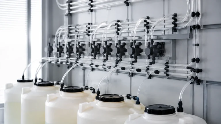
Flow Monitors
Flow Monitors
In industrial process control, flow monitors serve as critical safeguards and process indicators. Unlike high-precision flow meters that provide continuous volumetric or mass flow data, flow monitors are primarily designed to detect the presence, absence, or relative rate of fluid movement within a system. They are the "sentinels" of the piping network, ensuring that pumps do not run dry, cooling loops remain active, and chemical dosing occurs as scheduled.
For engineers and plant managers, selecting the correct flow monitoring technology is essential for maintaining operational uptime and preventing catastrophic equipment failure. This guide explores the fundamental principles, selection criteria, and installation best practices for industrial flow monitors.
Understanding Flow Monitoring Principles
Before selecting a device, it is vital to understand the physics governing how these instruments detect movement. Flow monitors generally operate on one of four physical principles: thermal dispersion, mechanical displacement, ultrasonic reflection/transit, or electromagnetic induction.
Thermal Dispersion Principle
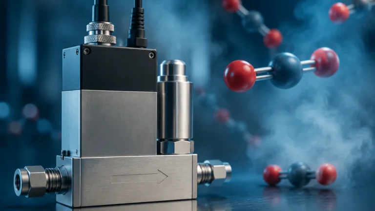
Thermal flow monitors utilize the heat transfer properties of the fluid. The sensor head typically contains two thermistors: one is heated, and the other serves as a reference for the ambient temperature of the media. When the fluid is stationary, the temperature differential between the two sensors remains constant. As the fluid begins to move, it carries heat away from the heated sensor (the cooling effect). The instrument measures the energy required to maintain the temperature differential or the change in the differential itself to determine the flow velocity. Because there are no moving parts, thermal monitors are highly valued for their reliability in harsh chemical environments.
Mechanical Displacement
Mechanical monitors rely on the physical force of the moving fluid. This is often achieved through a paddle wheel, a spring-loaded piston, or a swinging vane. As the fluid moves, it displaces the mechanical element. Once the element reaches a specific position, it triggers a microswitch or a reed switch. These are "go/no-go" devices, often used in simple water lines where high precision is less important than cost-effectiveness.
Ultrasonic Detection
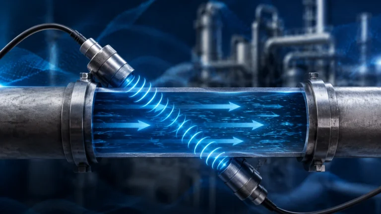
Ultrasonic flow monitors use sound waves to detect motion. There are two primary methods:
1. Doppler Effect: The sensor emits ultrasonic signals that reflect off bubbles or particles in the fluid. The frequency shift of the reflected signal is proportional to the flow velocity.
2. Transit-Time: The device measures the time difference between an ultrasonic pulse traveling with the flow and one traveling against it.
Electromagnetic Induction
Based on Faraday’s Law of Induction, electromagnetic monitors are used for conductive liquids. As a conductive fluid moves through a magnetic field generated by the monitor, it creates a voltage proportional to the velocity of the fluid. This method is non-intrusive and offers no resistance to the flow.
Key Technologies for Industrial Flow Monitors
Choosing the right technology depends heavily on the media properties (viscosity, conductivity, and cleanliness) and the specific goals of the application.
Thermal Flow Switches
Thermal switches are the industry standard for air, gas, and liquid monitoring where low-flow sensitivity is required. They are particularly effective in cooling water circuits for induction furnaces or monitoring the flow of lubricants in heavy machinery. Since they lack moving parts, they are resistant to wear and tear caused by suspended solids.
Paddle and Piston Switches
These are the workhorses of basic industrial automation. A paddle switch is ideal for large pipe diameters (DN50/2" and above) where a simple confirmation of flow is needed. Piston-style monitors are better suited for lower flow rates and can be calibrated for specific setpoints by changing the internal spring tension.
Ultrasonic Flow Monitors (Clamp-on)
For retrofitting existing systems without cutting into pipes, clamp-on ultrasonic monitors are the preferred solution. They are widely used in water treatment and the oil and gas industry to monitor flow in high-pressure lines where breaching the pipe wall would be risky or expensive.
Selection Criteria and Technical Specifications
When evaluating flow monitors, engineers must look beyond the price tag and consider the long-term compatibility with the process. The following table provides a comparison of common monitoring technologies based on typical industrial requirements.
| Feature | Thermal Dispersion | Mechanical (Paddle/Piston) | Ultrasonic (Transit-Time) | Electromagnetic |
| :— | :— | :— | :— | :— |
| Media Type | Liquids and Gases | Clean Liquids | Clean Liquids/Gases | Conductive Liquids |
| Moving Parts | None | Yes | None | None |
| Pressure Drop | Negligible | Moderate | Zero | Zero |
| Maintenance | Low | Medium (Wear/Clogging) | Low | Low |
| Sensitivity | High (Low flows) | Low | Medium | Medium |
| Typical Pipe Size | DN15 – DN300 | DN15 – DN600 | DN15 – DN3000 | DN10 – DN2000 |
Media Considerations
* Viscosity: High-viscosity fluids (like heavy oils) can impede mechanical paddles. Thermal monitors may require specific calibration for these fluids due to different heat transfer coefficients.
* Conductivity: Electromagnetic monitors require a minimum conductivity (usually >5 μS/cm). They will not work with deionized water or hydrocarbons.
* Cleanliness: Mechanical monitors are prone to jamming if the fluid contains stringy solids or high concentrations of grit.
Installation Considerations for Optimal Performance
A flow monitor is only as accurate as its installation. Even the most advanced thermal or ultrasonic sensor will fail if placed in an area of high turbulence or aeration.
1. Straight Pipe Runs: To ensure a stable flow profile, monitors should be installed in a straight section of pipe. A general rule of thumb is to allow for 10 diameters (10D) of straight pipe upstream and 5 diameters (5D) downstream from any elbows, valves, or pumps.
2. Orientation: For liquid applications, the pipe must be completely full. Installing the monitor on a vertical pipe with upward flow is often the best way to ensure the sensor is always submerged. Avoid downward flow in vertical pipes, as this can lead to partial filling and air pockets.
3. Sensor Depth: For insertion-type monitors, the sensor tip must reach the area of maximum velocity, typically the center of the pipe. If the sensor is too shallow, it may sit in the boundary layer where flow is sluggish and turbulent.
4. Avoid Cavitation: Do not install flow monitors immediately downstream of a pressure-reducing valve, as the resulting cavitation (vapor bubbles) can interfere with ultrasonic and thermal readings.
For engineers seeking a comprehensive range of measurement solutions, including level and flow instrumentation, you can review product options and application support on our Main Page.
Limitations and Operational Risks
While flow monitors are robust, they are not infallible. Understanding their limitations prevents false alarms and process interruptions.
* Scaling and Fouling: In water treatment or chemical processing, minerals or biological growth can build up on the sensor face. In thermal monitors, this acts as an insulator, slowing the response time. In mechanical monitors, it can cause the paddle to stick.
* Entrained Air: Bubbles in a liquid line can cause erratic readings in ultrasonic transit-time monitors and may cause thermal monitors to signal a "no-flow" condition because air carries heat away much less efficiently than liquid.
* Ambient Temperature Swings: While most modern thermal monitors are temperature-compensated, extreme fluctuations in the ambient environment (e.g., outdoor installations in sub-zero climates) can affect the electronics if not properly shielded.
Frequently Asked Questions (FAQs)
Q: Can a flow monitor replace a flow meter?
A: Generally, no. A flow monitor is designed to trigger an alarm or switch at a specific setpoint. If you need to know exactly how many liters per minute are passing through the pipe for billing or precise mixing, a flow meter is required.
Q: How often should flow monitors be calibrated?
A: For safety-critical applications (like pump dry-run protection), an annual check is recommended. Mechanical switches should be inspected more frequently for physical wear or debris accumulation.
Q: What is the difference between a flow switch and a flow monitor?
A: These terms are often used interchangeably. However, a "switch" usually refers to a device with a simple relay output (on/off), while a "monitor" might provide a visual display of flow velocity or a 4-20mA analog output representing the flow range.
Q: Can I use a thermal flow monitor for steam?
A: Standard thermal flow monitors are usually rated for liquids or gases. Steam requires specialized high-temperature sensors and considerations for phase changes. Always consult technical specifications before using a monitor in steam applications.
Conclusion
Flow monitors are indispensable tools for industrial process integrity. By understanding the underlying measurement principles—whether thermal, mechanical, or ultrasonic—and adhering to strict installation guidelines, facilities can significantly reduce the risk of equipment damage. When selecting a device, always prioritize the physical properties of your media and the specific environmental conditions of your plant. For further technical guidance and a full catalog of industrial sensing technology, visit the Main Page.