Liquid Level Switch Symbol
Liquid Level Switch Symbol
In the field of industrial process control and automation, the accurate representation of instruments on technical drawings is fundamental to engineering design, installation, and maintenance. The liquid level switch symbol serves as a universal language for engineers, allowing them to communicate the function, location, and electrical state of level detection devices within a system. Whether appearing on a Process and Instrumentation Diagram (P&ID) or an electrical schematic, these symbols provide critical information about how a system should respond when a fluid reaches a specific threshold.
Understanding these symbols requires a foundational knowledge of how different level switches operate and how they are integrated into control loops. This guide explores the various types of liquid level switches, their corresponding symbols across different standards, and practical considerations for their selection and application in industrial environments.
Principles of Liquid Level Detection
Before identifying the symbols used in documentation, it is essential to understand the physical principles that govern liquid level switches. A level switch is a point-level measurement device that provides a discrete output (typically an electrical contact closure or opening) when a liquid reaches a predetermined height. Unlike continuous level transmitters, which provide a constant signal (such as 4-20mA), a switch is binary—it is either "on" or "off."
Mechanical Float Switches
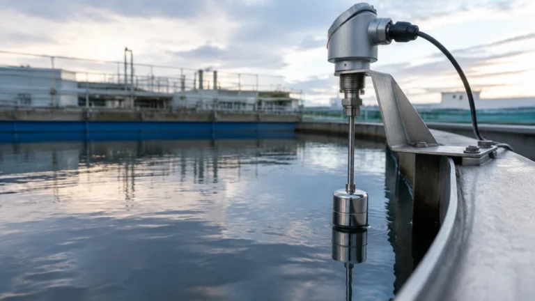
Float switches operate on the principle of buoyancy. A float, typically made of stainless steel or plastic, sits on the surface of the liquid. As the level rises or falls, the float moves. This movement triggers a mechanical switch or moves a magnet close to a reed switch, changing the electrical state. In technical drawings, the liquid level switch symbol for a float often incorporates a small circle or a hinged arm to represent the buoyant element.
Tuning Fork (Vibrating) Level Switches
Vibrating switches use a piezoelectric crystal to vibrate a metal fork at its natural frequency in the air. When the fork is submerged in liquid, the frequency changes or the vibration is damped. An internal electronic circuit detects this change and switches the output. These are highly reliable for liquids with varying densities and are often represented by symbols indicating a fork or a generic probe.
Capacitive Level Switches
Capacitive switches measure the change in capacitance between an electrode and the tank wall (or a second electrode). Since liquids have a different dielectric constant than air, the capacitance increases when the probe is covered. These are ideal for non-conductive liquids and solids.
Conductive Level Switches
Used primarily for conductive liquids like water or acids, these switches use a low-voltage current between two electrodes. When the liquid bridges the gap between the electrodes, the circuit is completed, and the switch is activated.
Standard Symbols in Industrial Documentation
The representation of a level switch varies depending on the type of drawing. The two most common standards are ISA (International Society of Automation) for P&IDs and IEC (International Electrotechnical Commission) for electrical schematics.
P&ID Symbols (ISA 5.1)
On a P&ID, instruments are typically represented by a circle (often called a "bubble"). Inside the bubble, letters indicate the function of the device. For a level switch, the first letter is always "L" (Level). The subsequent letters define the function:
* LS (Level Switch): A general designation for a level switch.
* LSH (Level Switch High): Activated when the level rises to a high point, often used for overflow prevention.
* LSL (Level Switch Low): Activated when the level falls to a low point, often used to protect pumps from running dry.
* LSHH / LSLL: High-High or Low-Low switches used for emergency shutdowns (ESD).
If the switch is mounted directly on the vessel, the bubble is usually attached to the vessel wall with a line. If it is a remote instrument, it may be shown separately with a signal line connecting it to the control system.
Electrical Schematic Symbols (IEC 60617)
In electrical wiring diagrams, the liquid level switch symbol focuses on the contact state. These symbols indicate whether the switch is "Normally Open" (NO) or "Normally Closed" (NC) in its shelf state (usually defined as the state when no liquid is present or the tank is empty).
* Normally Open (NO): The circuit is open until the liquid reaches the switch, at which point the contact closes.
* Normally Closed (NC): The circuit is closed until the liquid reaches the switch, at which point the contact opens.
The symbol usually consists of a standard switch contact with a small "flag" or "float" icon attached to the actuator arm, indicating that the movement is triggered by fluid level rather than a manual push-button or a limit switch.
Technical Selection Criteria
Choosing the correct level switch and ensuring its symbol is correctly specified on drawings depends on several process parameters. Engineers must evaluate the chemical compatibility, physical properties of the fluid, and the environmental conditions of the tank.
| Technology | Suitable Fluids | Max Temperature | Max Pressure | Typical Application |
| :— | :— | :— | :— | :— |
| Float Switch | Clean, non-coating liquids | Up to 200°C | Up to 40 bar | Water tanks, oil sumps |
| Tuning Fork | Liquids, slurries, powders | -50°C to 150°C | Up to 64 bar | Overfill protection, pump dry-run |
| Capacitive | Non-conductive liquids, oils | Up to 250°C | Up to 100 bar | Chemical processing, food & beverage |
| Conductive | Conductive liquids (Water, Acids) | Up to 100°C | Up to 10 bar | Wastewater, boiler level control |
For a comprehensive range of industrial measurement tools, engineers can Review product options and application support to find the specific hardware that matches their P&ID requirements.
Installation Considerations
Correct installation is as important as correct symbol identification. A misplaced switch can lead to "chattering" (rapid cycling of the switch) or failure to detect the level entirely.
1. Orientation: Float switches are often side-mounted or top-mounted. A side-mounted float requires a horizontal clearance, while a top-mounted float requires a vertical rod or cable. The liquid level switch symbol on a drawing should ideally reflect the mounting orientation to assist installers.
2. Turbulence and Agitation: In tanks with mixers or high-velocity inlets, turbulence can cause false switching. In these cases, a stilling well (a pipe surrounding the switch) is used to provide a calm surface for measurement.
3. Dead Band (Hysteresis): This is the difference between the point where the switch activates and the point where it resets. A wider dead band prevents the switch from toggling rapidly due to small ripples on the liquid surface.
4. Coating and Buildup: For sticky or viscous liquids, tuning forks or capacitive switches with "active shield" technology are preferred over mechanical floats, which can become stuck.

Limitations and Risks
While level switches are robust and cost-effective, they are not without limitations. Engineers must be aware of potential failure modes to ensure plant safety.
* Mechanical Wear: Float switches have moving parts that can wear out over time, especially in corrosive environments. Regular inspection is required to ensure the float has not been punctured or the hinge has not seized.
* Material Compatibility: The wetted parts of the switch must be compatible with the process fluid. For example, a 316 stainless steel probe may be suitable for water but could fail rapidly in concentrated hydrochloric acid.
* False Positives from Foam: Some technologies, like ultrasonic or certain capacitive switches, may struggle to distinguish between a layer of foam and the actual liquid surface. Tuning forks are generally more resistant to foam interference.
* Electrical Loading: Level switches usually have specific contact ratings (e.g., 5A at 250VAC). Exceeding these limits by connecting the switch directly to a high-power motor without a relay will cause the contacts to weld together, leading to a dangerous "fail-to-open" condition.
Frequently Asked Questions (FAQ)
Q: What is the difference between a level switch and a level transmitter?
A: A level switch provides a discrete (on/off) signal at a specific point. A level transmitter provides a continuous measurement of the level across a range (e.g., 0% to 100% full).
Q: How do I read a liquid level switch symbol on a P&ID if it has multiple lines?
A: Multiple lines usually indicate multiple switching points. For example, a single probe might have three internal switches: LSL (Low), LSH (High), and LSHH (High-High). Each will be shown as a separate bubble or a single bubble with multiple function codes.
Q: Can a level switch be used for solids?
A: Yes, certain technologies like tuning forks, rotating paddles, and capacitive probes are designed specifically for bulk solids and powders, though the liquid level switch symbol may remain similar in P&ID documentation.
Q: What does a dashed line connecting to a level switch symbol mean?
A: In ISA standards, a solid line usually represents a process connection or a pneumatic signal, while a dashed line represents an electrical signal or a data link to a PLC/DCS.
Conclusion
The liquid level switch symbol is more than just a graphic on a page; it is a critical specification that dictates the safety and efficiency of industrial processes. By understanding the underlying measurement principles—whether mechanical, frequency-based, or electrical—and adhering to standardized symbolic representations, engineering teams can ensure that their systems are built and maintained to the highest standards of accuracy. When selecting hardware, always cross-reference the process conditions with the instrument's technical specifications to ensure long-term reliability in the field.