Sonic Flow Meter
Sonic Flow Meter
In the landscape of industrial process control, the sonic flow meter—more commonly known as the ultrasonic flow meter—has emerged as a cornerstone technology for non-intrusive velocity measurement. Unlike traditional mechanical meters that rely on moving parts subject to wear and pressure drops, sonic flow meters utilize the properties of acoustic waves to determine the flow rate of liquids and gases. This guide provides a technical deep dive into the principles, selection criteria, and installation nuances of sonic flow meters, tailored for engineers and procurement professionals seeking reliable automation solutions.
Understanding Sonic Flow Measurement Principles
To effectively implement a sonic flow meter, one must first understand the two primary physical principles used to derive flow data: Transit-Time and Doppler Effect. Both methods utilize ultrasonic transducers (typically operating in the range of 0.5 to 4 MHz) but apply them to different fluid conditions.
Transit-Time Ultrasonic Principle
The transit-time method is the most prevalent in industrial applications involving clean fluids. This principle relies on the fact that sound waves traveling in the direction of fluid flow move faster than those traveling against it.
Two transducers are mounted on the pipe, acting as both transmitters and receivers. They send acoustic pulses back and forth. The time difference (Δt) between the upstream and downstream signals is directly proportional to the velocity of the fluid. The governing equation for velocity ($v$) can be simplified as:
$$v = K \cdot \frac{\Delta t}{t_{up} \cdot t_{down}}$$
Where $K$ is a calibration constant and $t$ represents the travel times. Because this method requires a clear acoustic path, it is best suited for water, chemicals, and oils with low concentrations of suspended solids or entrained air.
Doppler Effect Principle
The Doppler sonic flow meter operates on the principle of frequency shift. When an ultrasonic beam is projected into a moving fluid, it reflects off discontinuities such as suspended particles, sand, or gas bubbles. According to the Doppler Effect, the frequency of the reflected signal shifts in proportion to the velocity of the reflecting particles.
This method is essential for "dirty" liquids where transit-time signals would be attenuated or scattered. It is widely used in wastewater management, mining slurries, and dredging operations. Without these reflectors (particles or bubbles), a Doppler meter cannot function.
Transit-Time vs. Doppler: A Comparative Selection Table
Choosing the correct sonic flow meter depends heavily on the fluid's physical characteristics. The following table outlines the primary differences to assist in the initial evaluation phase.
| Feature | Transit-Time Meter | Doppler Meter |
| :— | :— | :— |
| Fluid Requirement | Clean liquids or gases (<1% solids) | Liquids with particles or bubbles (>100 ppm) |
| Typical Accuracy | ±0.5% to ±1% of flow rate | ±2% to ±5% of full scale |
| Pipe Sizes | 10 mm to over 5,000 mm | 25 mm to 3,000 mm |
| Primary Advantage | High precision, bidirectional measurement | Handles slurries and aerated liquids |
| Primary Limitation | Fails if fluid becomes too turbid | Fails in ultra-pure liquids |
| Typical Applications | Potable water, HVAC, hydrocarbon flow | Sewage, paper pulp, mining slurry |
Key Evaluation Criteria for Industrial Projects
When specifying a sonic flow meter for a project, several technical factors must be confirmed to ensure long-term accuracy and return on investment.
1. Pipe Material and Condition
Sonic waves must pass through the pipe wall in clamp-on configurations. Materials like carbon steel, stainless steel, and PVC are excellent conductors. However, pipes with internal liners (like concrete or thick rubber) or significant internal scaling can disrupt the signal. It is vital to confirm the pipe's outer diameter (OD) and wall thickness using ultrasonic thickness gauges before finalizing the meter selection.
2. Fluid Properties and Reynolds Number
Accuracy is influenced by the flow profile. Most sonic flow meters perform best in turbulent flow regimes (Reynolds Number > 10,000). In laminar flow, the velocity profile is parabolic, requiring the flow computer to apply sophisticated compensation factors. Additionally, the fluid’s sonic velocity (measured in m/s) varies with temperature and pressure, necessitating integrated temperature compensation in high-precision applications.
3. Transducer Mounting Styles
There are three common mounting configurations for clamp-on sensors:
* V-Mount: The signal reflects once off the opposite pipe wall. This is the standard for medium-sized pipes (50 mm to 400 mm).
* Z-Mount: Transducers are mounted on opposite sides of the pipe. This is used for large pipes or highly attenuative fluids where a shorter path is required.
* W-Mount: The signal reflects three times. This is used for very small pipes (below 50 mm) to increase the transit time and improve resolution.
Installation Considerations and Geometric Limits
Even the most advanced sonic flow meter will fail to provide accurate data if installed incorrectly. The most common source of error in the field is poor installation geometry.
Straight Pipe Requirements
To ensure a stable and predictable flow profile, sonic flow meters require a specific length of straight pipe upstream and downstream of the installation point.
* Upstream: Generally, a minimum of 10 pipe diameters (10D) is required after a single elbow.
* Downstream: A minimum of 5 pipe diameters (5D) is standard.
* Obstructions: If the meter is placed after a pump or a partially open valve, the upstream requirement may increase to 30D or 50D to allow turbulence to subside.
Mounting Position
On horizontal pipes, transducers should never be mounted at the top or bottom of the pipe. The top of the pipe often collects air bubbles, while the bottom collects sediment—both of which interfere with the acoustic signal. The ideal mounting position is at the 3 o'clock and 9 o'clock positions (the "sides" of the pipe).
Acoustic Coupling
For clamp-on meters, the air gap between the transducer and the pipe wall must be eliminated. This is achieved using an acoustic coupling agent (grease or gel). In permanent installations, solid epoxy or silicone couplants are used to prevent the gel from drying out over time, which would lead to signal loss.
Limitations and Common Operational Risks
While highly versatile, sonic flow meters are not a "one-size-fits-all" solution. Engineers must be aware of the following risks:
1. Signal Attenuation: High-viscosity liquids or fluids with extremely high concentrations of solids can absorb the acoustic energy, leading to a "Signal Lost" error.
2. Ambient Noise: Industrial environments with heavy vibration or high-frequency electrical noise can interfere with the sensitive electronics of the flow computer. Shielded cabling and proper grounding are mandatory.
3. Temperature Extremes: Standard transducers are often rated up to 120°C. For high-temperature steam or thermal oil applications, specialized high-temperature transducers and mounting hardware are required.
4. Pipe Wall Integrity: If the pipe is severely corroded or pitted on the inside, the acoustic beam may scatter unpredictably. In such cases, an inline (wetted) sonic flow meter may be a better choice than a clamp-on model.
Integration with Industrial Automation Systems
Modern sonic flow meters are rarely standalone devices. They serve as critical data nodes in broader automation frameworks. Most units offer 4-20mA analog outputs, pulse outputs for totalization, and digital protocols like Modbus RS485, HART, or Profibus.
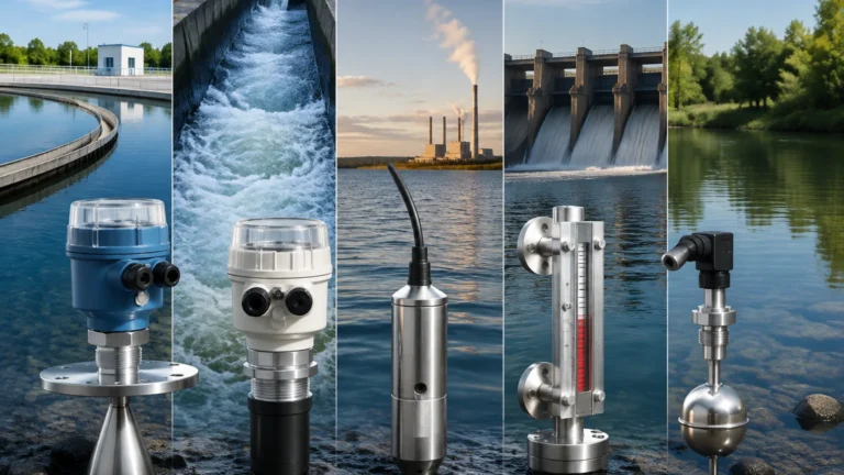
In many industrial setups, flow measurement is intrinsically linked to level measurement. For instance, in open channel flow monitoring or large tank inventory management, combining flow data with accurate level readings is essential for mass balance calculations. Professionals looking to optimize their measurement loops often consult comprehensive resources for both flow and level technologies. For a broader look at industrial measurement instruments, including radar and ultrasonic level sensors that complement flow systems, you can explore the Main Page of specialized manufacturers like Welk.
Frequently Asked Questions (FAQs)
Q: Can a sonic flow meter measure gas flow?
A: Yes, but it requires specific high-frequency transducers and a transit-time meter designed for gas. Gas has a much lower acoustic impedance than liquid, making the signal harder to detect.
Q: How often does a clamp-on sonic flow meter need calibration?
A: Because there are no moving parts to wear out, the electronic calibration remains stable for years. However, the acoustic coupling gel should be inspected annually to ensure it hasn't dried out, and a zero-flow check is recommended during maintenance shutdowns.
Q: Does pipe wall thickness affect accuracy?
A: Yes. The flow computer calculates the fluid velocity based on the internal diameter of the pipe. If the wall thickness entered into the device is incorrect, the resulting flow rate calculation will be biased. Always use a thickness gauge for verification.
Q: Can I use a sonic flow meter on a partially full pipe?
A: Generally, no. Most sonic flow meters assume a full pipe to calculate the cross-sectional area. If the pipe is partially full, the meter will over-report the flow. For partially full pipes, an area-velocity flow meter that incorporates a level sensor is required.
Conclusion
The sonic flow meter represents a significant leap forward in process efficiency, offering a non-invasive, low-maintenance solution for a wide range of industrial fluids. By understanding the distinction between transit-time and Doppler principles and adhering to strict installation geometries, facilities can achieve high-precision flow monitoring without the downtime associated with cutting pipes. As industrial automation continues to evolve, the integration of reliable flow and level measurement remains the foundation of optimized production and resource management.