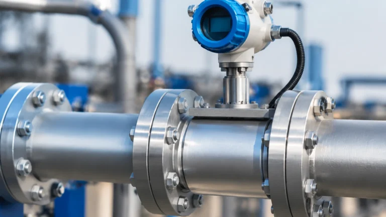
In Line Water Flow Sensor
In Line Water Flow Sensor
In industrial process control and water management, the in line water flow sensor serves as a fundamental component for monitoring, regulating, and billing fluid consumption. Unlike external or clamp-on devices, an in-line sensor is integrated directly into the piping architecture, ensuring that the fluid passes through or across the sensing element. This direct contact allows for high levels of accuracy and repeatability, which are essential for applications ranging from chemical dosing to municipal water distribution.
Selecting the correct in line water flow sensor requires a deep understanding of the underlying measurement principles, the hydraulic conditions of the installation site, and the physical properties of the water being measured. This guide provides a technical overview of common flow measurement technologies, selection criteria, and practical installation guidelines for engineering professionals.
Understanding In-Line Water Flow Sensor Technologies
Before specifying a sensor, it is critical to understand how different technologies interact with the fluid. Each principle offers distinct advantages depending on whether the water is ultrapure, potable, or contains suspended solids.
Electromagnetic Flow Meters (Magmeters)
Electromagnetic flow meters operate based on Faraday’s Law of Electromagnetic Induction. This law states that a conductor moving through a magnetic field produces an electrical signal directly proportional to the velocity of the conductor. In this application, the water acts as the conductor.
* Principle: The sensor consists of a non-conductive liner and two electrodes. Magnetic coils generate a field across the pipe diameter. As conductive water flows through the field, a voltage is induced and captured by the electrodes.
* Requirements: The water must have a minimum conductivity level, typically $>5 μS/cm$. This makes magmeters ideal for raw water, wastewater, and process water, but unsuitable for deionized or distilled water.
* Advantages: No moving parts, zero pressure drop, and high resistance to wear.
Ultrasonic Flow Meters (Transit-Time)
In-line ultrasonic sensors utilize sound waves to determine fluid velocity. While clamp-on versions exist, in-line "spool-piece" ultrasonic sensors are preferred for high-precision industrial applications because the transducer path is factory-calibrated.
* Principle: Two transducers send and receive ultrasonic pulses diagonally across the pipe. The pulse traveling with the flow moves faster than the pulse traveling against it. The time difference (Δt) is proportional to the flow velocity.
* Requirements: Best suited for clean water with minimal aeration or suspended solids, as bubbles can scatter the ultrasonic signal.
* Advantages: Extremely wide turndown ratios and no obstruction to the flow path.
Turbine Flow Meters
Turbine sensors are mechanical devices that translate the kinetic energy of the water into rotational movement.
* Principle: A multi-bladed rotor is suspended in the flow stream. As water passes, the rotor spins at a speed proportional to the flow velocity. A pick-up coil or Hall-effect sensor detects the passage of the rotor blades and generates a frequency signal.
* Requirements: The water must be clean to prevent debris from clogging the rotor or damaging the bearings.
* Advantages: High accuracy in steady-state flow conditions and relatively low cost for smaller pipe sizes.
Vortex Flow Meters
Vortex shedding sensors utilize the Kármán vortex street principle.
* Principle: A "bluff body" (a non-streamlined object) is placed in the center of the flow. As water hits this body, vortices are shed alternately from each side. The frequency of these vortices is directly proportional to the flow velocity.
* Requirements: Requires a minimum Reynolds number to ensure stable vortex shedding.
* Advantages: Highly durable and capable of handling high-temperature water or steam.
Selection Criteria for Industrial Applications
When evaluating an in line water flow sensor for a specific project, engineers must look beyond the initial price point and consider the total cost of ownership and application compatibility. For a comprehensive overview of industrial measurement instruments, including level and flow solutions, visit the Main Page of our technical resource center.
1. Fluid Characteristics
* Conductivity: If the water is non-conductive, electromagnetic meters are excluded.
* Viscosity: High-viscosity fluids can affect the Reynolds number, impacting vortex and turbine meter accuracy.
* Particulate Load: Abrasive solids will wear down turbine blades, while heavy sludge may coat the electrodes of a magmeter.
2. Flow Range and Turndown Ratio
The turndown ratio is the ratio of the maximum flow to the minimum flow that the sensor can measure accurately. For example, a sensor with a 100:1 turndown ratio and a max flow of 100 m³/h can measure down to 1 m³/h. Ultrasonic and electromagnetic meters typically offer much higher turndown ratios than mechanical turbine meters.
3. Accuracy and Repeatability
In B2B industrial environments, accuracy is usually expressed as a percentage of the actual reading (e.g., ±0.5% of Rate). Repeatability is equally important for process consistency, ensuring the sensor provides the same output for the same flow rate over time.
Technical Comparison Table
| Technology | Accuracy (Typical) | Pressure Drop | Moving Parts | Min. Conductivity Required | Ideal Application |
| :— | :— | :— | :— | :— | :— |
| Electromagnetic | ±0.2% to ±0.5% | Negligible | No | Yes (>5 μS/cm) | Wastewater, Slurries, Raw Water |
| Ultrasonic | ±0.5% to ±1.0% | Negligible | No | No | Potable Water, Cooling Loops |
| Turbine | ±0.25% to ±0.5% | Moderate | Yes | No | Fuel, Clean Distilled Water |
| Vortex | ±0.7% to ±1.0% | Low to Moderate | No | No | High-Temp Water, Steam |
Installation Best Practices and Considerations
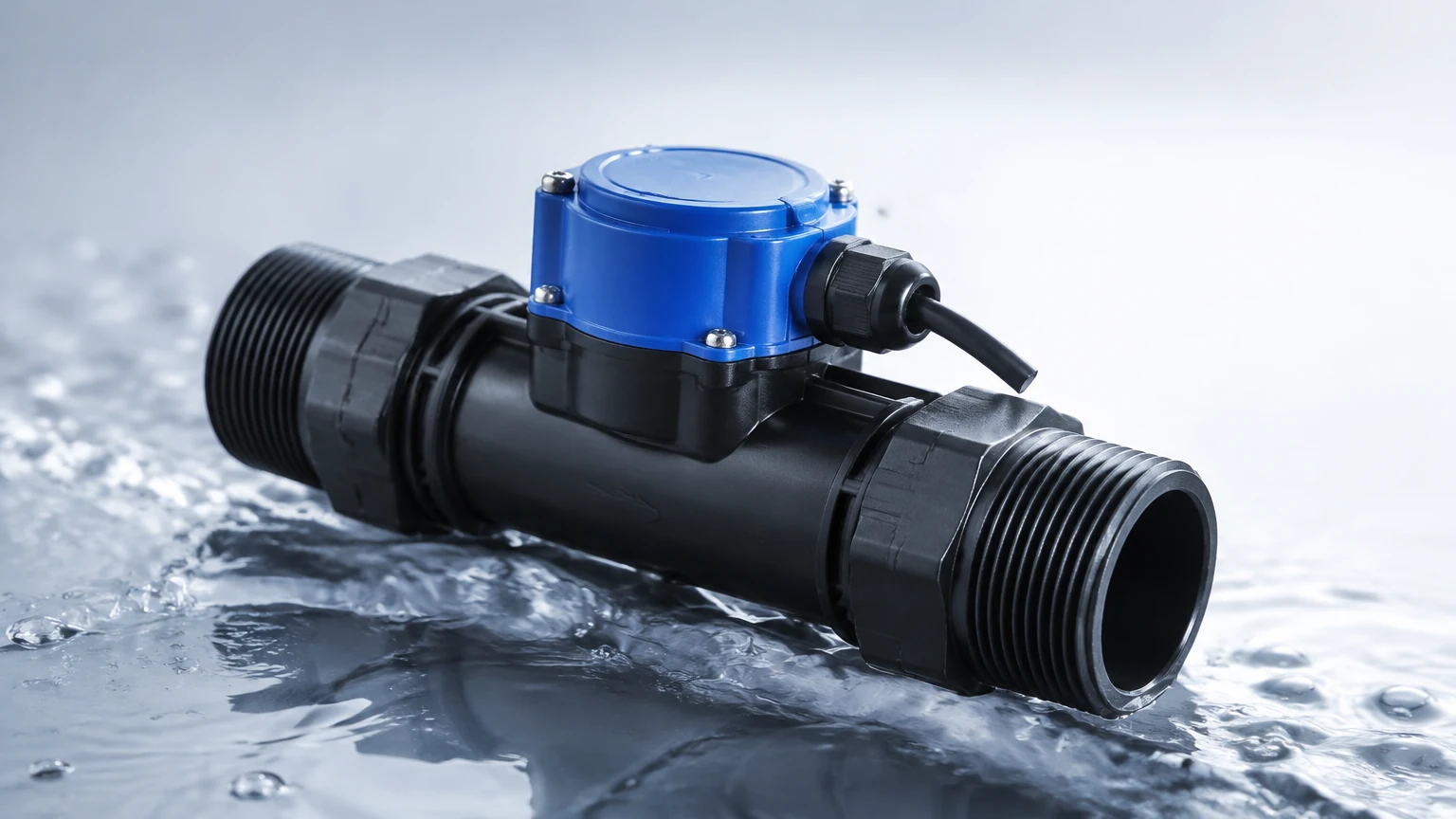
Even the most advanced in line water flow sensor will fail to perform if installed incorrectly. The goal of installation is to provide the sensor with a stable, fully developed flow profile.
Straight Pipe Requirements
Flow sensors are sensitive to turbulence caused by elbows, valves, and pumps. To mitigate this, manufacturers specify minimum straight-run distances upstream and downstream of the sensor, often expressed in pipe diameters (D).
* Upstream: Typically 5D to 10D (e.g., for a 100 mm pipe, 500 mm to 1000 mm of straight pipe is needed before the sensor).
* Downstream: Typically 2D to 5D.
Mounting Orientation
* Horizontal Pipes: The sensor should be installed in a position where the pipe is always full. Avoid the highest point of a piping system where air pockets might collect.
* Vertical Pipes: Flow should ideally move upward. This ensures the pipe remains full and prevents air bubbles from being trapped against the sensing elements.
Grounding and Interference
For electromagnetic meters, proper grounding is non-negotiable. If the pipe is plastic or lined, grounding rings must be used to ensure the fluid and the sensor share the same electrical potential. Failure to do so results in "noise" that can fluctuate the flow readings.
Common Risks and Operational Limitations
1. Cavitation: If the pressure drops too low at the sensor location, water may vaporize, forming bubbles that damage turbine blades and cause massive errors in ultrasonic and vortex readings.
2. Scaling and Fouling: Over time, minerals (like calcium carbonate) or biological growth can build up on the sensor walls. In turbine meters, this increases friction; in magmeters, it can insulate the electrodes.
3. Air Entrainment: Small amounts of air can significantly displace water volume, leading to over-reading in mechanical meters or signal loss in ultrasonic meters.
4. Vibration: Excessive pipe vibration can interfere with the sensors in vortex meters, which rely on detecting small pressure fluctuations.
Pre-Purchase Checklist for Engineering Projects
Before finalizing the specification for an in line water flow sensor, project managers and engineers should confirm the following data points:
* Pipe Specifications: Confirm the exact internal diameter (ID), material, and flange rating (e.g., ANSI 150# or PN16).
* Flow Profile: Identify the minimum, normal, and maximum expected flow rates in m³/h or liters per minute (LPM).
* Fluid Chemistry: Determine the pH, conductivity, and percentage of solids.
* Environmental Conditions: Check the ambient temperature and whether the installation area requires an IP68 rating (for submersion) or ATEX/IECEx certification (for hazardous areas).
* Output Requirements: Decide if the system needs a simple 4-20mA analog signal, a pulse output for totalizing, or digital protocols like Modbus RS485 or HART.
Frequently Asked Questions (FAQ)
Q: Can an in line water flow sensor measure flow in both directions?
A: Many electromagnetic and ultrasonic sensors are inherently bi-directional and can be configured to measure and totalize flow in both forward and reverse directions. Mechanical turbine meters are typically uni-directional.
Q: How often do these sensors need calibration?
A: In regulated industries (like municipal water), annual calibration is often required. In general industrial use, electromagnetic and ultrasonic sensors are very stable and may only require verification every 2-3 years, whereas turbine meters may require more frequent checks due to mechanical wear.
Q: What is the impact of pipe size on sensor choice?
A: For small pipes (under 25 mm / 1 inch), turbine and vortex sensors are very cost-effective. For large diameter pipes (above 300 mm / 12 inches), the cost of electromagnetic meters increases significantly, making ultrasonic spool-pieces or insertion-style meters more attractive options.
Q: Do I need a strainer before the sensor?
A: If you are using a turbine flow meter, a 40-mesh or finer strainer is highly recommended to protect the rotor from debris. For magmeters or ultrasonic meters, a strainer is generally unnecessary unless the solids are large enough to physically block the pipe.
By carefully matching the sensor technology to the specific hydraulic and chemical environment of the application, facility managers can ensure long-term reliability and precise data for their water management systems.