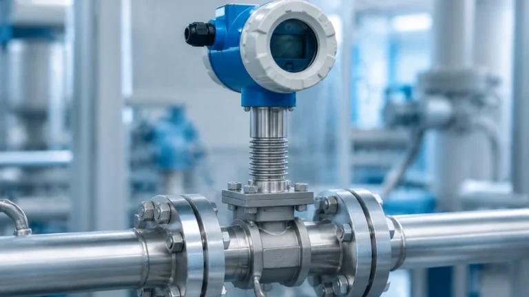
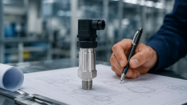
Level Instrumentation
Level Instrumentation
In the landscape of industrial automation, level instrumentation serves as a critical component for ensuring process safety, inventory management, and operational efficiency. Whether managing bulk solids in a silo, corrosive chemicals in a storage tank, or wastewater in a treatment facility, the accurate measurement of liquid or solid levels is fundamental to preventing overflows, protecting equipment, and optimizing production cycles. This guide explores the diverse technologies within the field of level instrumentation, providing engineering insights into their principles, selection, and application.
Understanding Core Measurement Principles
Before selecting a specific instrument, it is essential to understand the physical principles that govern different measurement technologies. Level instrumentation is generally categorized into continuous measurement and point level detection.
Radar Level Measurement
Radar technology is widely regarded as the gold standard for high-accuracy applications. It operates on the Time of Flight (ToF) principle or Frequency Modulated Continuous Wave (FMCW) technology.
* Non-Contact Radar: These sensors emit microwave pulses (typically in the 26 GHz or 80 GHz range) toward the medium. The signals reflect off the surface and return to the antenna. The instrument calculates the distance based on the time interval between emission and reception. High-frequency 80 GHz radar is particularly effective in narrow tanks or vessels with internal obstructions due to its narrow beam angle.
* Guided Wave Radar (GWR): This contact-based method uses a probe (cable or rod) to guide the microwave pulse directly to the medium. This is advantageous in applications with low dielectric constants or where surface turbulence and foam might dissipate a non-contact signal.
Ultrasonic Level Measurement
Ultrasonic sensors utilize sound waves rather than electromagnetic waves. The transducer emits an ultrasonic pulse (usually between 40 kHz and 70 kHz) that travels through the air, reflects off the surface, and returns. Because the speed of sound is affected by air temperature, these instruments typically include integrated temperature sensors to compensate for variations and maintain accuracy. They are cost-effective solutions for water and wastewater applications but are limited in high-pressure or vacuum environments where sound cannot propagate effectively.
Hydrostatic Level Measurement
Hydrostatic transmitters measure the pressure exerted by a liquid column at a specific depth. The principle follows the formula: $P = \rho \cdot g \cdot h$, where $P$ is pressure, $\rho$ is the density of the liquid, $g$ is gravity, and $h$ is the height of the liquid. These sensors are often used in vented tanks or deep wells. In pressurized vessels, a differential pressure (DP) transmitter is required to subtract the overhead gas pressure from the total pressure at the bottom.
Magnetic Level Gauges
Magnetic level gauges (MLGs) provide a visual indication and can be equipped with transmitters for remote monitoring. They consist of a bypass chamber mounted to the side of a vessel. Inside the chamber, a float containing a permanent magnet moves with the liquid level. Outside the chamber, a series of magnetic flags or flaps flip as the float passes, providing a clear, high-visibility mechanical display that requires no power for local viewing.
Technology Selection and Application Matrix
Choosing the right level instrumentation requires a thorough analysis of the media properties and vessel conditions. The following table provides a comparison of common technologies used in industrial settings.
| Technology | Media Type | Typical Range | Accuracy | Key Advantages | Primary Limitations |
| :— | :— | :— | :— | :— | :— |
| Radar (80 GHz) | Liquids, Solids, Corrosives | Up to 120m | ±1 mm | Non-contact, unaffected by dust/vapor | Higher initial cost |
| Ultrasonic | Water, Chemicals | 0.25m – 15m | ±0.25% | Cost-effective, easy to install | Sensitive to foam and vacuum |
| Hydrostatic | Liquids, Slurries | 1m – 200m | ±0.1% to 0.5% | Reliable for deep wells/sumps | Affected by density changes |
| Guided Wave Radar| Liquids, Interfaces | Up to 30m | ±2 mm | Excellent for low dielectric media | Contact-based (probe fouling) |
| Magnetic Gauge | Clean Liquids | 0.3m – 6m | ±5 mm | No power for local display | Not suitable for high-viscosity |
Critical Installation Considerations
Even the most advanced level instrumentation will fail to provide accurate data if installed incorrectly. Engineering teams must account for the following factors during the design phase:
1. The "Dead Zone" or Blocking Distance
Every sensor has a minimum distance near the transducer face where measurement is impossible. For ultrasonic sensors, this is typically 0.2m to 0.6m. For radar, it is much smaller but still present. The instrument must be mounted high enough so that the maximum liquid level never enters this zone.
2. Nozzle Geometry
When mounting sensors on tank nozzles, the nozzle height and diameter must be considered. If a nozzle is too narrow or too long, the signal (especially in ultrasonic and radar) may reflect off the nozzle walls rather than the process media, causing false echoes. Using an extension or a higher-frequency radar with a narrower beam can mitigate this.
3. Obstructions and Turbulence
Internal structures such as agitators, heating coils, and ladders can create "ghost echoes." Modern digital level meters often include "False Signal Suppression" software to map out these static reflections. However, it is best practice to install the sensor at least 200mm to 500mm away from the tank wall and away from the filling inlet to avoid turbulence and signal scattering.
4. Environmental Sealing
In chemical and outdoor applications, the ingress protection (IP) rating is vital. For B2B industrial environments, IP67 or IP68 is standard for sensors exposed to heavy rain or washdown procedures. Furthermore, in hazardous areas, instruments must carry appropriate ATEX, IECEx, or SIL certifications.
Addressing Limitations and Environmental Factors
No single level instrumentation technology is a universal solution. Understanding the constraints of each is necessary for long-term reliability.
* Vapor and Steam: Ultrasonic waves are significantly attenuated by heavy steam or dense vapors, which change the composition of the air through which the sound travels. Radar is generally unaffected by these conditions.
* Dielectric Constant ($ε_r$): Radar relies on the reflectivity of the media. Materials with a low dielectric constant (like certain oils or liquefied gases) reflect less energy. In these cases, Guided Wave Radar or high-sensitivity non-contact radar is required.
* Foam: Heavy, dense foam can absorb both ultrasonic and radar signals. If foam is a constant factor, hydrostatic sensors or magnetic level gauges are often more reliable as they measure the liquid phase beneath the foam.
* Pressure and Temperature: Hydrostatic sensors are sensitive to pressure changes in the vessel headspace. Ultrasonic sensors cannot function in a vacuum. For extreme temperatures (e.g., molten salts or cryogenic liquids), specialized cooling fins or remote seals are necessary for the electronics.
For a comprehensive overview of available technologies and to find specific models tailored to these challenges, engineers can Review product options and application support at the Welk Main Page.
Frequently Asked Questions (FAQ)
Q: How do I choose between a level switch and a continuous level transmitter?
A: A level switch is used for point detection (e.g., high-level alarm or pump start/stop). A continuous level transmitter provides a real-time 4-20mA or digital signal (HART, Modbus) representing the exact level throughout the tank's height. Use switches for safety redundancy and transmitters for process control.
Q: Does the density of the liquid affect radar measurement?
A: No. Radar measurement is based on the dielectric constant and the speed of light, making it independent of density changes. This is a major advantage over hydrostatic sensors, which must be recalibrated if the liquid density changes.
Q: Can level instrumentation be used for solids?
A: Yes, but with caveats. Solids like grain, cement, or plastic pellets often form cones or ruts rather than a flat surface. 80 GHz radar is the preferred choice for solids due to its ability to penetrate dust and its narrow beam, which can be aimed to average the surface profile.
Q: What maintenance is required for level sensors?
A: Non-contact sensors like radar and ultrasonic require very little maintenance as they do not touch the media. Contact sensors (GWR, Hydrostatic, Magnetic) should be inspected periodically for buildup, corrosion, or mechanical wear on floats.
Conclusion
Selecting the appropriate level instrumentation is a balance between technical requirements, environmental constraints, and budget. By understanding the underlying physics—whether it be the microwave reflection of radar, the pressure-depth relationship of hydrostatic sensors, or the acoustic properties of ultrasonic waves—engineers can implement solutions that provide high accuracy and long-term stability. As a professional manufacturer, Welk provides a wide array of industrial instruments designed for the most demanding applications in water treatment, oil and gas, and chemical processing. Ensuring that the chosen device is matched to the specific dielectric, pressure, and temperature profiles of the process is the most effective way to guarantee operational success.