Flow in a Curved Channel
Flow in a Curved Channel
In industrial fluid management and civil engineering, the behavior of flow in a curved channel presents a unique set of hydraulic challenges that differ significantly from straight-line flow. Whether in wastewater treatment plants, irrigation systems, or cooling water circuits in power plants, curves are often unavoidable due to site topography or facility layout. Understanding the mechanics of how water and other process liquids move through these bends is essential for accurate level measurement, flow rate calculation, and the long-term structural integrity of the channel itself.
For engineers and operators, the primary concern with flow in a curved channel is the departure from uniform flow conditions. In a straight channel, the water surface is typically horizontal across the cross-section. However, as soon as the fluid enters a bend, centrifugal forces and secondary flow patterns emerge, complicating the use of standard level sensors and flow meters. This article explores the principles of curved channel hydraulics and provides a technical framework for selecting and installing instrumentation in these complex environments.
The Physics of Flow in a Curved Channel
To effectively manage liquids in a non-linear path, one must first understand the three-dimensional nature of the flow. When fluid moves through a bend, it is subject to several physical phenomena that impact how a level meter perceives the "true" height of the liquid.
Centrifugal Force and Superelevation
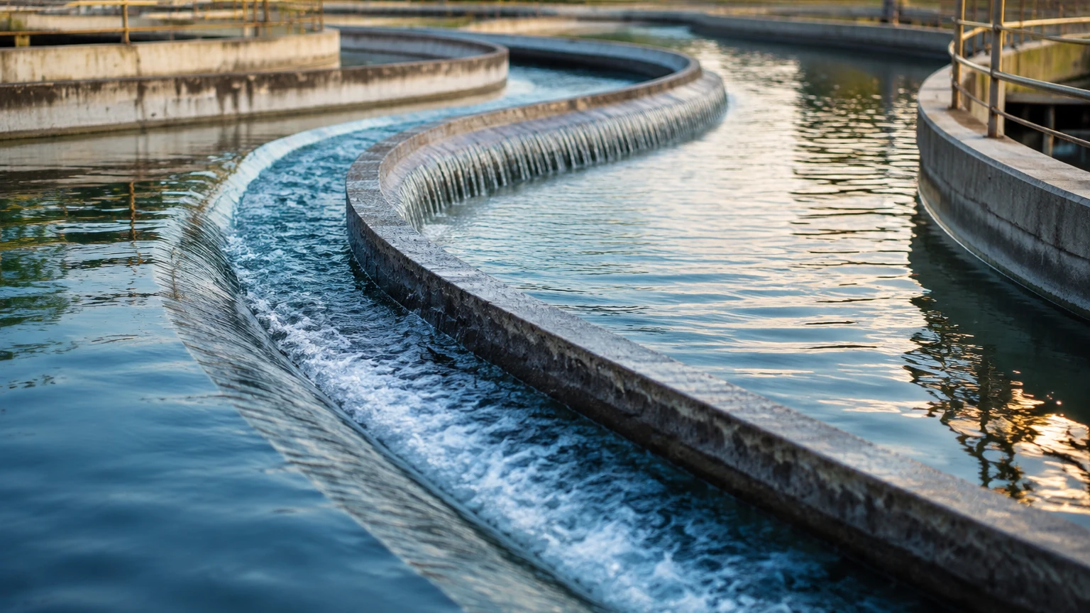
As fluid enters a curve, centrifugal force acts upon the mass of the liquid, pushing it toward the outer bank. Because the fluid is constrained by the channel walls, this outward pressure results in a rise in the water surface elevation along the outer wall and a corresponding drop along the inner wall. This phenomenon is known as superelevation.
In practical terms, if a level sensor is mounted on the outer radius of a curve, it will report a significantly higher level than a sensor mounted on the inner radius. For B2B applications requiring precise inventory or flow data, this discrepancy can lead to substantial errors in volume calculations. The magnitude of superelevation depends on the velocity of the flow, the width of the channel, and the radius of the curve.
Secondary Flow and Helical Motion
The interaction between centrifugal forces and the boundary layer at the bottom of the channel creates a "secondary flow." Near the surface, the fluid moves toward the outer bank. Near the bed of the channel, where friction reduces velocity and centrifugal force is weaker, a pressure gradient drives the fluid back toward the inner bank.
This creates a helical (corkscrew-like) flow pattern. This secondary circulation is responsible for redistributing momentum and can cause localized turbulence and surface ripples. For ultrasonic or radar level meters, this increased surface agitation can interfere with signal reflection, leading to "noise" in the data.
Measurement Principles and Technology Recommendations
When dealing with flow in a curved channel, the choice of measurement technology is critical. Standard hydrostatic or non-contact sensors must be applied with an understanding of the hydraulic profile. At Welk, we emphasize matching the instrument's strengths to the specific turbulence and surface characteristics of the application.
Radar Level Meters
Radar level meters are often the preferred choice for curved channels with high velocity. Because they use high-frequency electromagnetic waves, they are less affected by the air temperature fluctuations and vapors often found in industrial channels.
* Advantage: Non-contact measurement avoids the debris and scouring common in curves.
* Consideration: In a curved channel, the radar beam must be positioned where the surface is most representative of the mean depth, or the superelevation must be mathematically compensated.
Ultrasonic Level Sensors
Ultrasonic sensors are cost-effective solutions for many open-channel applications. They work by emitting sound pulses and measuring the time of flight.
* Advantage: Highly reliable in stable environments.
* Limitation: In curves where high-velocity flow causes significant spray or foam, the ultrasonic signal can be attenuated or scattered. They are best suited for curved channels with lower Froude numbers (slower, subcritical flow).
Hydrostatic Level Transmitters
These sensors measure the pressure exerted by the liquid column. In a curved channel, they are typically installed in a stilling well to protect them from the lateral forces of the flow.
* Advantage: Immune to surface foam and turbulence.
* Limitation: The sensor measures pressure, not just depth. In a curve, the dynamic pressure component can influence the reading if the sensor is not properly shielded or positioned.
Selection Table for Curved Channel Instrumentation
The following table provides a comparison of common technologies used to monitor flow in a curved channel based on typical industrial requirements.
| Technology | Accuracy in Curves | Turbulence Resistance | Maintenance Needs | Ideal Application |
| :— | :— | :— | :— | :— |
| Radar (80GHz) | High | Excellent | Low | High-velocity industrial effluents, chemical channels. |
| Ultrasonic | Moderate | Fair | Medium | General water treatment, irrigation bends. |
| Hydrostatic | High | Good (with stilling well) | Medium | Deep channels, locations with heavy surface foam. |
| Magnetic Flow Meter | N/A (In-line) | N/A | Low | Closed-pipe sections of a curved system. |
| Level Switches | High (Point-level) | Good | Low | Overfill protection on the outer bank of a curve. |
Installation Considerations for Curved Channels
Proper installation is the most significant factor in ensuring the accuracy of data gathered from a curved channel. If the project allows, the Main Page of the instrumentation plan should prioritize placing sensors in straight sections at least 10 channel widths upstream of a curve. However, when measurement must occur within the curve, the following guidelines apply:
1. Positioning Along the Cross-Section
To minimize the impact of superelevation, the sensor should ideally be located at the centerline of the channel. At the centerline, the water level is closest to the "mean" depth that would exist in a straight channel of the same slope and roughness. If mounting at the centerline is not possible due to bridge or walkway constraints, the sensor offset from the centerline must be recorded so that a correction factor can be applied to the flow calculations.
2. Avoiding the "Splash Zone"
In high-velocity curves, the outer wall often experiences significant splashing and wave run-up. Non-contact sensors (Radar/Ultrasonic) should be mounted high enough to avoid being coated by spray, which can foul the transducer face. For radar units, using a drip shield or a specialized antenna design can mitigate the effects of condensation and splashing.
3. Stilling Wells for Hydrostatic Sensors
If using a hydrostatic transmitter, a stilling well is mandatory in a curved channel. The well dampens the oscillations caused by secondary flow and protects the sensor from the physical impact of debris that is naturally pushed toward the outer bank by centrifugal force.
4. Accounting for Bed Scour and Sedimentation
The helical flow in a curve tends to erode the outer bank (scour) and deposit sediment on the inner bank (point bars). If your level-to-flow conversion depends on a fixed cross-sectional area, you must periodically survey the channel bed. Changes in the bed geometry will invalidate your flow tables even if the level measurement is accurate.
Limitations and Common Risks
Measuring flow in a curved channel is inherently less accurate than measuring in a straight reach. Engineers should be aware of the following risks:
* Unstable Rating Curves: Most flow calculations rely on a Stage-Discharge relationship (rating curve). In a curve, this relationship can shift depending on the flow regime (subcritical vs. supercritical).
* Surface Slant: In extreme cases, the water surface slant can be so pronounced that a non-contact sensor's beam hits the surface at an angle, reducing the returned signal strength. This is particularly problematic for ultrasonic sensors with wide beam angles.
* Vortex Formation: In tight bends, flow separation can occur at the inner wall, leading to the formation of vortices. These vortices create air entrainment, which can cause ultrasonic sensors to lose their signal completely.
Frequently Asked Questions (FAQs)
Q: How do I calculate the superelevation in a curved channel?
A: A common engineering approximation for superelevation ($Δh$) is $Δh = (v^2 · B) / (g · R)$, where $v$ is the average velocity (m/s), $B$ is the channel width (m), $g$ is the acceleration due to gravity (9.81 m/s²), and $R$ is the radius of the curve (m).
Q: Can I use a weir or flume in a curved channel?
A: It is strongly discouraged. Weirs and flumes require a uniform velocity distribution to function according to their standard formulas. A curve disrupts this distribution. If a flume must be used, it should be placed in a straight section significantly upstream of the bend.
Q: Which sensor is best for a curved channel with heavy foam?
A: Radar level meters or hydrostatic transmitters are best. Ultrasonic sensors often fail in foamy conditions because the foam absorbs the sound waves. Radar, however, penetrates foam more effectively to reach the liquid surface.
Q: Does the radius of the curve affect the choice of technology?
A: Yes. A "sharp" bend (small radius) creates more turbulence and greater superelevation. In sharp bends, non-contact radar is generally superior due to its ability to handle surface agitation. In "lazy" or large-radius bends, the flow is closer to uniform, and ultrasonic sensors may be sufficient.
Conclusion
Managing flow in a curved channel requires a departure from standard "straight-line" thinking. By accounting for the physics of superelevation and secondary helical flow, engineers can specify instrumentation that provides reliable data despite the inherent hydraulic complexities. While radar level meters offer the highest performance in these challenging environments, the success of any installation depends on strategic positioning and a thorough understanding of the channel's specific flow characteristics.
For professional-grade measurement solutions and technical support in selecting the right instrument for your process, visit the Welk Main Page to explore our full range of radar, ultrasonic, and hydrostatic level technologies.