Sensor for Oil Tank
Sensor for Oil Tank
In industrial environments, selecting the correct sensor for oil tank applications is a critical decision that impacts operational safety, inventory accuracy, and environmental compliance. Whether managing crude oil in large storage terminals, refined fuels in distribution hubs, or lubricants in manufacturing facilities, engineers must navigate a complex landscape of physical properties and environmental variables. This guide provides a technical overview of the measurement principles, selection criteria, and installation requirements for industrial oil level sensors.
Core Measurement Principles for Oil Storage
Before selecting a specific sensor for oil tank monitoring, it is essential to understand the underlying physical principles used to detect liquid levels. Oil presents unique challenges, including low dielectric constants, varying viscosities, and the potential for vapor or foam formation.
Time-of-Flight (ToF) Principles
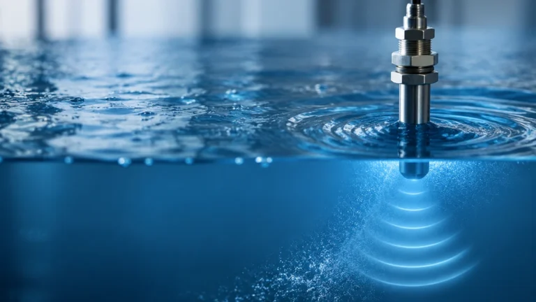
Time-of-Flight is the primary principle behind radar and ultrasonic sensors. The device emits a signal (electromagnetic for radar, acoustic for ultrasonic) that travels to the oil surface and reflects back to the sensor. The distance is calculated using the formula:
*Distance = (Speed of Wave × Travel Time) / 2*
In oil applications, radar is often preferred over ultrasonic because electromagnetic waves are not affected by the air density or vapor layers common in fuel tanks.
Hydrostatic Pressure
Hydrostatic measurement relies on the principle that the pressure at the bottom of a tank is directly proportional to the height of the liquid column above it. The relationship is defined as:
*P = ρ × g × h*
Where *P* is pressure, *ρ* (rho) is the density of the oil, *g* is gravity, and *h* is the height. For this method to remain accurate in oil tanks, the density must be constant, or the system must include temperature compensation, as oil density changes significantly with temperature fluctuations.
Magnetic Displacement
Magnetic level gauges utilize a float containing an internal magnet. As the oil level changes, the float moves along a bypass chamber or a guide tube. This movement either flips external magnetic flags for visual indication or triggers a magnetostrictive sensor to provide a continuous 4-20mA or digital signal.
Radar Technology: The Industrial Standard
Radar is widely considered the most reliable sensor for oil tank applications due to its non-contact nature and high precision. There are two primary types used in the industry: non-contact radar and guided wave radar (GWR).
Non-Contact Radar (80GHz and 26GHz)
Modern 80GHz high-frequency radar sensors offer narrow beam angles, which are ideal for avoiding internal tank obstructions like heating coils or agitators. Because oil has a relatively low dielectric constant ($ε_r ≈ 1.9$ to 4.0), the reflected signal is weaker than it would be for water. High-frequency sensors provide the sensitivity required to detect these faint reflections reliably.
Guided Wave Radar (GWR)
GWR uses a physical probe (cable or rod) to guide the microwave signal to the liquid surface. This technology is particularly effective for low-dielectric oils because the probe concentrates the energy, ensuring a stronger return signal. GWR is also excellent for measuring the interface between oil and settled water at the bottom of a tank.
Ultrasonic and Hydrostatic Alternatives
While radar is versatile, other technologies serve specific niches in oil level monitoring.
Ultrasonic Sensors
Ultrasonic sensors are cost-effective solutions for atmospheric oil tanks containing non-volatile fluids like hydraulic oil or lubricants. However, they are generally avoided for volatile fuels (gasoline, diesel) because the presence of heavy vapors can change the speed of sound, leading to significant measurement errors. Most industrial ultrasonic sensors for oil include temperature compensation to mitigate air density changes.
Hydrostatic Transmitters
Hydrostatic sensors are favored for their simplicity and ease of maintenance. In large crude oil tanks, a pressure transmitter installed at the bottom flange provides a rugged measurement. To ensure accuracy, engineers must account for the specific gravity of the oil. If the tank is pressurized, a differential pressure (DP) transmitter is required to subtract the top-side vapor pressure from the total bottom pressure.
Selection Matrix for Oil Tank Sensors
Choosing the right sensor for oil tank installations depends on the specific media and tank conditions. The following table summarizes common industrial recommendations.
| Technology | Typical Accuracy | Max Range | Ideal Media | Limitations |
| :— | :— | :— | :— | :— |
| 80GHz Radar | ±1 mm | 30m – 120m | Crude oil, refined fuels | Higher initial cost |
| Guided Wave Radar | ±2 mm | Up to 30m | Lubricants, interface | Probe fouling in heavy wax |
| Ultrasonic | ±0.25% FS | 10m – 15m | Non-volatile oils | Affected by vapor/vacuum |
| Hydrostatic | ±0.1% FS | N/A (Pressure) | Heavy fuel oil, diesel | Requires constant density |
| Magnetic Gauge | ±5 mm | 6m | High temp/pressure oil | Mechanical moving parts |
For a broader look at how these technologies integrate into automated systems, you may review product options and application support on our Main Page.
Engineering Installation and Configuration
Correct installation is as vital as technology selection. Even the most advanced sensor for oil tank monitoring will fail if positioned incorrectly.
1. Nozzle Height and Diameter: For non-contact radar, the nozzle should be as short as possible. If the nozzle is too long or narrow, it can create "ringing" or parasitic reflections that mask the actual oil level.
2. Dead Zones (Blocking Distance): Every sensor has a minimum detection distance (dead zone) near the transmitter head. For ultrasonic sensors, this is typically 250mm to 500mm (approx. 10 to 20 inches). Ensure the tank's maximum fill level does not enter this zone.
3. Avoid Obstructions: Sensors should not be installed directly above ladder rungs, inflow pipes, or heating elements. If obstructions are unavoidable, use a radar sensor with a narrow beam angle or a guided wave radar.
4. Stilling Wells: In tanks with heavy turbulence or foam, installing the sensor inside a stilling well (a vertical pipe) can provide a calm surface for measurement. This is common in large-scale oil terminal storage.
Addressing Limitations and Operational Risks
When deploying a sensor for oil tank use, engineers must account for several environmental and chemical factors:
* Dielectric Constant (ε_r): Most oils are non-conductive and have low dielectric constants. If the $ε_r$ is below 1.4, standard radar may struggle. In these cases, GWR or high-sensitivity 80GHz radar is mandatory.
* Vapor and Condensation: Oil tanks often contain hydrocarbon vapors. In outdoor installations, temperature swings can cause condensation on the sensor face. Choosing a sensor with a PTFE (Teflon) or PEEK lens can help shed droplets and prevent buildup.
* Paraffin and Wax Buildup: In crude oil applications, paraffin wax can accumulate on probes or floats. Hydrostatic or non-contact radar sensors are generally preferred here as they are less susceptible to mechanical failure caused by coating.
* Hazardous Areas: Most oil storage environments are classified as Zone 0, 1, or 2 (or Class I, Div 1/2). Sensors must carry appropriate ATEX, IECEx, or UL certifications to ensure they do not become an ignition source.
Frequently Asked Questions (FAQ)
Q: Can I use the same sensor for both oil and water?
A: While many sensors can detect both, the calibration will differ. For hydrostatic sensors, the density change between oil (~0.8 g/cm³) and water (1.0 g/cm³) will cause an error of 20% if not adjusted. Radar sensors can detect the interface between the two if the oil layer is at least 50mm to 100mm thick.
Q: How does temperature affect oil level measurement?
A: Temperature affects the volume and density of oil. If you are measuring mass or volume for fiscal transfer, you must use a sensor for oil tank monitoring that includes or integrates with a temperature probe (RTD) to perform real-time compensation.
Q: Is non-contact radar better than guided wave radar for oil?
A: It depends on the tank. Non-contact radar is better for maintenance because it has no parts touching the oil. However, GWR is superior for very low dielectric fluids or when there is heavy foam on the surface.
Q: What is the maximum pressure these sensors can handle?
A: Standard industrial radar and hydrostatic sensors can typically handle up to 40 bar (approx. 580 PSI), though specialized high-pressure versions are available for liquefied petroleum gas (LPG) or heavy industrial processes reaching 100+ bar.
Conclusion
Selecting a sensor for oil tank applications requires a balanced evaluation of the oil's chemical properties, the tank's physical structure, and the required accuracy. For most modern industrial needs, 80GHz radar provides the most robust performance, while hydrostatic and magnetic gauges remain reliable choices for specific pressure and temperature requirements. By following proper installation guidelines and accounting for dielectric and vapor limitations, operators can ensure long-term reliability and safety in their oil storage operations.