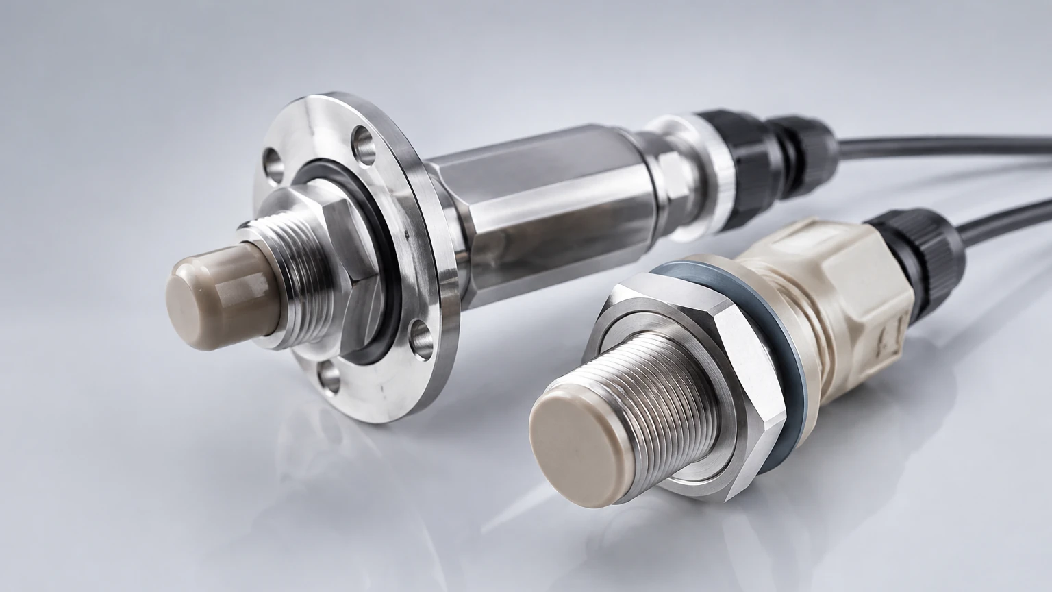
Cip Sensors
Cip Sensors
In the food, beverage, pharmaceutical, and chemical industries, maintaining hygiene is not merely a regulatory requirement but a fundamental pillar of process integrity. Clean-in-Place (CIP) systems allow for the internal cleaning of tanks, pipes, and vessels without the need for disassembly. However, the presence of aggressive cleaning agents, high-pressure sprays, and extreme temperature fluctuations poses significant challenges for instrumentation.
Cip sensors, specifically level measurement devices designed for these environments, must provide high accuracy while withstanding caustic soda, nitric acid, and steam sterilization. Selecting the correct sensor requires an understanding of both the measurement physics and the mechanical requirements of hygienic design.
Measurement Principles in CIP Environments
Level measurement in CIP-capable vessels typically relies on three primary physical principles: electromagnetic wave reflection (Radar), acoustic reflection (Ultrasonic), and hydrostatic pressure. Each principle interacts differently with the cleaning cycle.
Radar Level Measurement (ToF)
Radar sensors emit high-frequency electromagnetic pulses (typically in the 80 GHz range). These pulses reflect off the surface of the liquid and return to the sensor. The time-of-flight (ToF) determines the distance.
In CIP applications, 80 GHz radar is preferred because its narrow beam angle allows it to be installed in small vessels or near internal obstructions like spray balls and agitators without interference. Because radar waves are unaffected by air temperature, pressure, or the presence of steam, they remain accurate during hot cleaning cycles and steaming (SIP) processes.
Ultrasonic Level Measurement
Ultrasonic sensors use sound waves to measure the distance to the product surface. While cost-effective, they are sensitive to the medium's atmosphere. During a CIP cycle, the air temperature inside a tank can rise from 20°C to over 85°C rapidly. Since the speed of sound changes with temperature, ultrasonic sensors require integrated temperature compensation. Furthermore, heavy steam or foam—common during cleaning—can attenuate the sound signal, leading to signal loss.
Hydrostatic Pressure Measurement
Hydrostatic sensors measure the pressure exerted by the liquid column. This pressure is directly proportional to the level and the density of the fluid. For CIP applications, these sensors must use a flush-mounted diaphragm. A traditional recessed diaphragm would create a "dead space" where bacteria could grow, as the cleaning fluid cannot reach the internal cavity effectively.
Key Evaluation Criteria for Cip Sensors
When evaluating cip sensors for industrial automation, engineers must prioritize mechanical integrity and material compatibility alongside measurement accuracy.
1. Hygienic Design and Certification
Sensors must comply with international standards such as 3-A Sanitary Standards or EHEDG (European Hygienic Engineering & Design Group). These certifications ensure that the sensor's geometry prevents the accumulation of product and that all surfaces are accessible to the cleaning media.
2. Material Compatibility
The wetted parts of the sensor must be chemically resistant to both the process media and the cleaning agents. Common materials include:
* Stainless Steel 316L (1.4404/1.4435): The standard for sensor housings and diaphragms due to its corrosion resistance.
* PTFE/TFM: Used for radar antennas and gaskets because of its nearly universal chemical resistance and non-stick properties.
* PEEK (Polyether ether ketone): Often used for sensor tips and insulators where high thermal stability and mechanical strength are required.
3. Surface Roughness
To prevent microbial attachment, the surface finish of wetted parts must be extremely smooth. A typical requirement for CIP-compliant sensors is a surface roughness (Ra) of less than 0.8 μm. For pharmaceutical applications, this may be further reduced to Ra < 0.4 μm, often achieved through electropolishing.
Technical Selection Table
The following table compares the most common technologies used for level measurement in CIP-regulated vessels.
| Feature | 80 GHz Radar | Ultrasonic | Hydrostatic (Flush) | Point Level Switch |
| :— | :— | :— | :— | :— |
| Accuracy | ±1 mm | ±2 mm to 10 mm | ±0.1% of span | ±1 mm |
| Steam Resistance | Excellent | Poor | Good | Excellent |
| Foam Tolerance | Moderate to High | Low | High | High (Tuning Fork) |
| Max Temperature | Up to 200°C | Up to 80°C | Up to 150°C | Up to 150°C |
| Mounting | Top-mounted | Top-mounted | Side/Bottom-mounted | Side/Top-mounted |
| Typical Cost | High | Low to Medium | Medium | Low |
Installation Considerations
Proper installation is critical to ensure that the sensor does not become a source of contamination and that it provides reliable data during the cleaning process.
Avoiding Dead Legs
A "dead leg" is an area in the piping or vessel where the cleaning fluid does not circulate with sufficient velocity to ensure cleanliness. When installing cip sensors, the length of the mounting nozzle should be kept as short as possible. A common rule of thumb is the 1:1 or 2:1 ratio (length to diameter), though hygienic fittings like Tri-Clamp or Varivent® are designed to eliminate this issue entirely.
Spray Ball Interference
In many tanks, CIP spray balls are used to distribute cleaning fluid. Radar and ultrasonic sensors should be positioned so that the spray pattern does not hit the sensor face directly with high pressure, which could cause mechanical damage or temporary false readings. However, the sensor face *must* be reached by the cleaning fluid to ensure it is sanitized.
Thermal Shock
During a CIP cycle, a sensor might be exposed to a 90°C caustic wash followed immediately by a 15°C cold water rinse. This thermal shock can cause condensation inside the sensor housing if it is not properly sealed (IP69K rating is recommended) or lead to diaphragm fatigue in hydrostatic sensors. Choosing sensors with high thermal shock resistance is vital for long-term reliability.
Limitations and Common Risks
While modern cip sensors are robust, several factors can compromise their performance:
1. Condensation: In high-humidity environments, water droplets can form on the sensor face. While 80 GHz radar can typically see through thin films of condensation, heavy droplets can cause signal attenuation. Look for sensors with convex lens designs that encourage droplets to run off.
2. Chemical Attack: Repeated exposure to concentrated nitric acid or phosphoric acid can degrade certain sealing materials (like EPDM or FKM) over time. Regular inspection of seals is a mandatory maintenance task.
Vacuum Collapse: After a hot CIP or SIP cycle, the rapid cooling of the vessel can create a vacuum. If the sensor's diaphragm is not designed to handle negative pressure, it may be permanently deformed.
Frequently Asked Questions (FAQ)
Q: Can I use a standard industrial sensor for CIP applications?
A: Generally, no. Standard sensors often have threads or gaskets that create crevices where bacteria can grow. They may also use materials that cannot withstand the high temperatures and aggressive chemicals used in CIP.
Q: What is the difference between CIP and SIP?
A: CIP (Clean-in-Place) refers to cleaning with chemicals and water. SIP (Sterilization-in-Place) involves using saturated steam at temperatures typically around 121°C to 140°C to kill microorganisms. Sensors must be rated for both if the process requires sterilization.
Q: How do I handle foam during the cleaning cycle?
A: If foam is a consistent issue, hydrostatic pressure sensors are the most reliable as they measure the liquid mass and are unaffected by surface foam. If non-contact measurement is required, high-frequency radar is the best alternative.
Conclusion
Selecting the right cip sensors involves a balance between measurement precision and the harsh realities of the cleaning cycle. Radar technology offers the most versatile performance in the face of steam and temperature shifts, while hydrostatic sensors provide a robust solution for dense foams and pressurized vessels. Engineers should always verify that the selected instrument carries the necessary hygienic certifications and is constructed from materials compatible with their specific cleaning chemistry.
For more detailed technical specifications and to explore a full range of industrial measurement hardware, you can Review product options and application support on our Main Page. Our team provides customized OEM/ODM services to ensure that your level measurement solutions meet the strictest global standards for accuracy and hygiene.