Fixed Doppler Flow Switch
Fixed Doppler Flow Switch
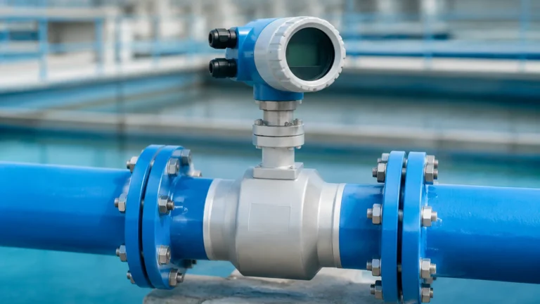
In industrial process control, monitoring the movement of fluids within a closed piping system is critical for protecting equipment and ensuring operational efficiency. A fixed Doppler flow switch serves as a non-invasive solution designed to detect flow velocity and trigger an alarm or relay when the flow exceeds or falls below a specific threshold. Unlike traditional mechanical switches, these ultrasonic devices operate from the outside of the pipe, making them ideal for challenging fluids that are corrosive, abrasive, or contain high concentrations of solids.
This guide explores the engineering principles, selection criteria, and installation best practices for fixed Doppler flow switches, providing a technical foundation for engineers and plant managers seeking reliable flow detection solutions.
Measurement Principles of Doppler Technology
The operation of a fixed Doppler flow switch is based on the Doppler Effect, a physical phenomenon where the frequency of a wave changes relative to an observer moving compared to the source of the wave. In the context of liquid flow measurement, the switch utilizes ultrasonic sound waves.
The Ultrasonic Signal Path
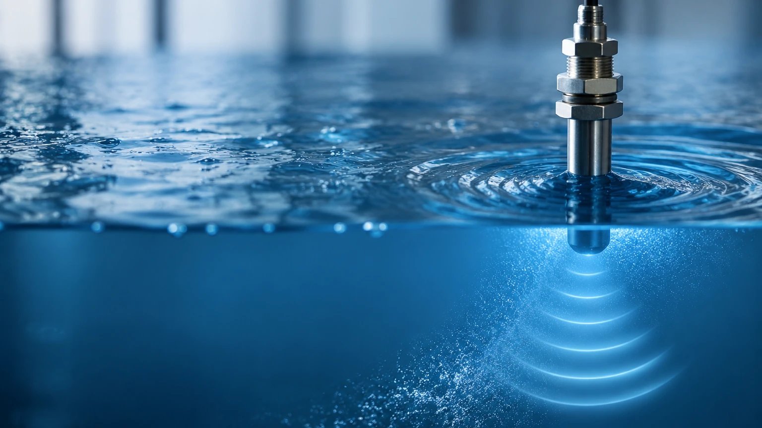
A Doppler flow switch typically consists of a transducer (or a pair of transducers) mounted on the exterior of a pipe. The device transmits an ultrasonic signal at a known frequency into the liquid. For the Doppler effect to occur, the liquid must contain "reflectors"—these are typically suspended solids, sediment, or entrained gas bubbles.
When the ultrasonic signal hits these moving reflectors, it is bounced back toward the receiver. Because the particles are moving with the fluid, the frequency of the reflected signal is shifted. If the fluid is moving toward the sensor, the frequency increases; if it is moving away, the frequency decreases.
Frequency Shift Calculation
The relationship between the frequency shift and the flow velocity is defined by the following principle:
Δf = 2f₀ (v/c) cos θ
Where:
* Δf is the frequency shift.
* f₀ is the transmitted frequency.
* v is the velocity of the fluid.
* c is the speed of sound in the fluid.
* θ is the angle of the ultrasonic beam relative to the flow direction.
The internal circuitry of the fixed Doppler flow switch processes this frequency shift to determine the flow velocity. If the calculated velocity crosses a user-defined set point, the switch activates a relay (usually a dry contact SPDT or DPDT) to signal a control system or shut down a pump.
Key Components and Design Features
A fixed Doppler flow switch is engineered for permanent installation and continuous monitoring. Its design usually comprises two main elements:
1. The Transducer Assembly: Often housed in a rugged, chemically resistant enclosure (such as stainless steel or high-density plastic), the transducers are clamped to the pipe. Some designs use a single-head transducer containing both the transmitter and receiver, while others use a dual-head configuration.
2. The Electronics Enclosure: This unit contains the signal processor, user interface, and output relays. In a fixed installation, this enclosure is typically wall-mounted or integrated into a control panel. It converts the raw ultrasonic data into a usable switching signal.
Modern units often include adjustable time delays to prevent "nuisance tripping" caused by momentary turbulence or air pockets, and sensitivity adjustments to fine-tune the device for different concentrations of suspended solids.
Technical Selection Criteria
Choosing the correct fixed Doppler flow switch requires an understanding of the process fluid and the piping environment. Because the technology relies on reflections, it is not a universal solution for all liquids.
Fluid Requirements
The most critical requirement for a Doppler flow switch is the presence of particles or bubbles. Generally, the fluid must contain at least 100 parts per million (ppm) of suspended solids or bubbles, typically sized 75 microns or larger.
* Suitable Fluids: Raw sewage, aerated water, chemical slurries, mining tailings, and pulp stock.
* Unsuitable Fluids: Deionized water, ultra-pure chemicals, and very clean treated water with no entrained air.
Pipe Material and Condition
The ultrasonic signal must pass through the pipe wall and into the fluid with minimal attenuation.
* Materials: Best results are achieved with sonically conductive materials like carbon steel, stainless steel, copper, and most plastics (PVC, HDPE).
* Liners: Pipes with liners can be problematic. If a liner (like rubber or cement) is not perfectly bonded to the outer pipe wall, an air gap may exist, which completely blocks the ultrasonic signal.
* Wall Thickness: Standard sensors usually accommodate pipe walls up to 25 mm (approx. 1 inch), though specialized high-power sensors exist for thicker conduits.
Comparison Table: Doppler vs. Other Technologies
| Feature | Fixed Doppler Flow Switch | Thermal Dispersion Switch | Mechanical Paddle Switch |
| :— | :— | :— | :— |
| Installation | Non-invasive (Clamp-on) | Invasive (Insertion) | Invasive (In-line) |
| Fluid Type | Dirty/Aerated Liquids | Clean or Dirty Liquids | Clean Liquids |
| Pressure Drop | Zero | Minimal | Moderate |
| Maintenance | Extremely Low | Low | High (Moving parts) |
| Pipe Size Range | 12.5 mm to 5000 mm | 12.5 mm to 600 mm | Specific to valve body |
| Corrosion Risk | None | Low (Wetted parts) | High |
Installation Considerations
Proper installation is paramount for the accuracy of a fixed Doppler flow switch. Unlike magnetic or turbine meters, the Doppler switch is sensitive to the flow profile and the acoustic coupling between the sensor and the pipe.
Location and Straight Run Requirements
To ensure a stable flow profile, the sensor should be installed on a straight section of pipe. Turbulence caused by valves, elbows, or pumps can lead to erratic switching.
* Upstream: Provide a minimum of 10 pipe diameters (10D) of straight run before the sensor.
* Downstream: Provide a minimum of 5 pipe diameters (5D) of straight run after the sensor.
If the pipe is vertical, the flow should ideally be upward to ensure the pipe remains completely full and that bubbles are evenly distributed.
Acoustic Coupling
Since air is a poor conductor of high-frequency sound, there must be no air gap between the transducer face and the pipe surface.
1. Surface Preparation: The pipe surface must be cleaned of rust, scale, and loose paint. A smooth, flat surface is required.
2. Coupling Compound: A specialized acoustic couplant (silicone grease or epoxy) is applied to the transducer face. For fixed installations, a permanent adhesive or high-temperature grease is often used to ensure long-term contact.
3. Mounting Position: On horizontal pipes, mount the sensors at the 3 o'clock or 9 o'clock positions. Avoid the top of the pipe (where air bubbles collect) and the bottom (where sediment settles), as both can interfere with the signal.
Limitations and Practical Constraints
While the fixed Doppler flow switch is a powerful tool, engineers must be aware of its operational boundaries:
* Laminar vs. Turbulent Flow: Doppler switches perform most reliably in turbulent flow conditions (typically Reynolds numbers above 4000), where particles are well-distributed across the pipe cross-section.
* Minimum Velocity: Most switches require a minimum flow velocity to function, often around 0.1 m/s to 0.15 m/s (0.3 to 0.5 fps).
* Temperature Extremes: Standard transducers are usually rated up to 100°C (212°F). For high-temperature applications, specialized standoff mounts or high-temp transducers are required to protect the piezoelectric elements.
* Sonic Velocity Variations: Changes in the liquid's temperature or concentration can change the speed of sound in the medium, slightly affecting the velocity calibration, though this is often negligible for simple switching applications.
Frequently Asked Questions (FAQs)
Q: Can a Doppler flow switch work on a pipe that is only half full?
A: No. The pipe must be completely full of liquid for the ultrasonic signal to travel across the medium and return to the sensor. If the pipe is partially empty, the signal will reflect off the air-liquid interface and fail to provide a reading.
Q: How do I know if my fluid has enough "reflectors"?
A: A general rule of thumb is that if the liquid is opaque or cloudy, it likely has enough particles. If the liquid is clear but "sparkly" (indicating micro-bubbles), it may also work. For borderline cases, a portable Doppler meter can be used to test the site before installing a fixed unit.
Q: Does pipe vibration affect the switch?
A: While Doppler technology is robust, extreme mechanical vibration can introduce noise into the electronics. It is best to mount the electronics enclosure away from high-vibration equipment and ensure the transducers are clamped securely.
Q: Can I use a Doppler switch on plastic-lined carbon steel pipe?
A: Only if the liner is fully bonded to the steel. If there is any gap, even a microscopic one, the ultrasonic signal will be reflected at the boundary and will not enter the fluid.
Conclusion
The fixed Doppler flow switch represents a reliable, low-maintenance solution for flow detection in industrial environments where invasive sensors would fail due to clogging or corrosion. By understanding the necessity of suspended reflectors and adhering to strict installation protocols regarding straight pipe runs and acoustic coupling, facilities can achieve precise flow monitoring without interrupting the process.
For engineers evaluating specific models or seeking customized solutions for complex industrial automation needs, it is advisable to consult with manufacturers who offer a range of ultrasonic and hydrostatic technologies. You can Review product options and application support on our Main Page to find the right instrumentation for your specific chemical, water treatment, or oil and gas application.