Ultrasonic Level Sensor Datasheet
Ultrasonic Level Sensor Datasheet: A Technical Guide for Engineering Selection
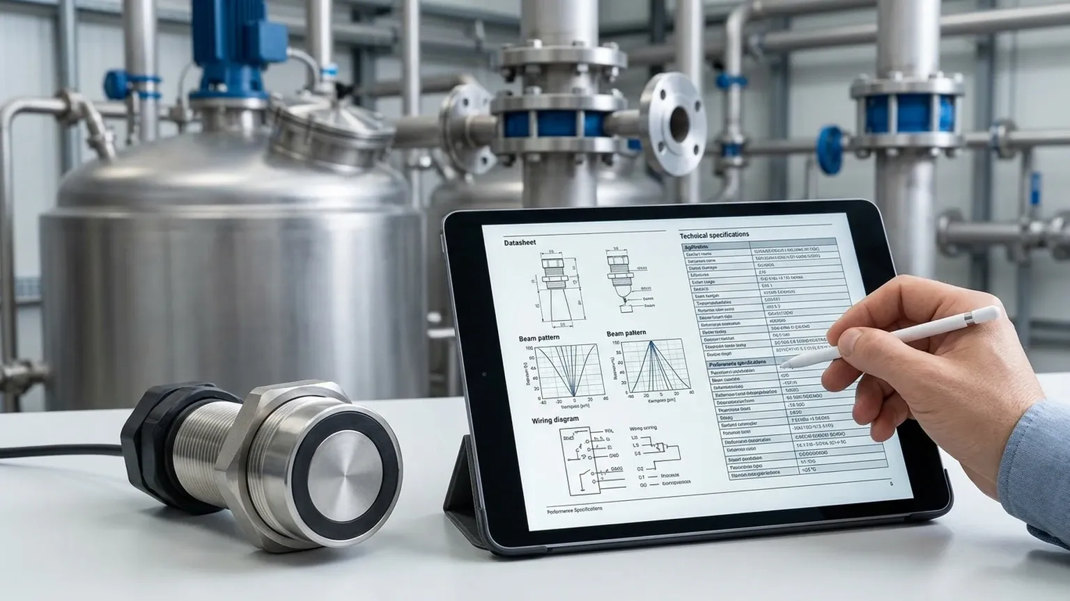
In the realm of industrial process control, selecting the correct instrumentation is a critical step toward ensuring operational efficiency and safety. The ultrasonic level sensor datasheet serves as the primary technical contract between the manufacturer and the end-user, detailing the performance boundaries, electrical requirements, and physical limitations of the device. For engineers and procurement specialists, understanding how to interpret these specifications is essential for successful integration into water treatment, chemical processing, or industrial automation systems.
As a professional manufacturer, Welk provides a range of Ultrasonic Level Meters designed to meet diverse industrial needs. This guide explores the fundamental principles of ultrasonic measurement and provides a deep dive into the technical parameters found in a standard datasheet to help you make an informed selection.
The Core Principle of Ultrasonic Measurement
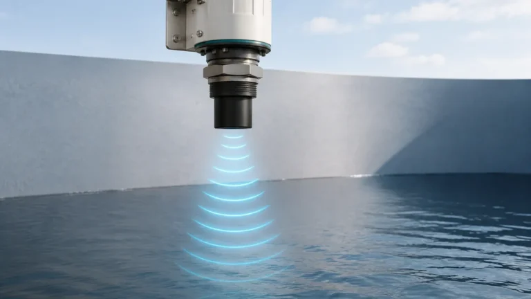
Before analyzing a datasheet, it is vital to understand the physics governing the device. Ultrasonic level sensors operate on the "Time of Flight" (ToF) principle. The sensor’s transducer emits high-frequency sound pulses (typically between 20 kHz and 200 kHz). These sound waves travel through the air, strike the surface of the medium (liquid or solid), and reflect back to the transducer.
The sensor measures the time interval between the emission of the pulse and the reception of the echo. Since the speed of sound in air is a known constant (approximately 343 m/s at 20°C), the distance to the surface can be calculated using the formula:
Distance = (Speed of Sound × Time) / 2
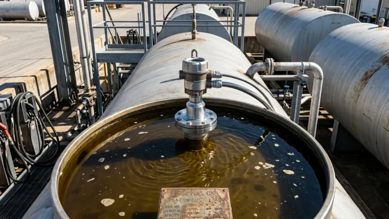
The internal microprocessor then subtracts this distance from the total tank height (programmed during calibration) to determine the actual level or volume of the material. Because this is a non-contact method, it is highly valued for applications involving corrosive, viscous, or hazardous liquids where contact-based sensors might fail or require excessive maintenance.
Decoding the Ultrasonic Level Sensor Datasheet
When reviewing an ultrasonic level sensor datasheet, several key parameters dictate whether a specific model is suitable for your application. Below are the most critical specifications to evaluate.
1. Measuring Range and the "Dead Zone"
Every ultrasonic sensor has a specified measuring range, typically defined by a minimum and maximum distance.
* Maximum Range: This is the furthest distance the pulse can travel and return with sufficient strength to be detected. For industrial models, this often ranges from 5 meters to 30 meters.
* Dead Zone (Blocking Distance): This is a critical limitation of all ultrasonic sensors. It refers to the small area directly in front of the transducer face where the sensor cannot accurately measure. This occurs because the transducer needs a fraction of a millisecond to stop vibrating (ringing) after emitting a pulse before it can switch to receiving mode. Typical dead zones range from 0.25 meters to 0.8 meters. If the liquid level enters this zone, the sensor will provide erratic readings or a "full" error signal.
2. Beam Angle
The beam angle (usually measured at the -3dB point) defines the spread of the ultrasonic pulse. A datasheet might specify a beam angle of 5° to 12°.
* Narrow Beam (e.g., 5°-8°): Ideal for tall, narrow tanks or vessels with internal obstructions like ladders, agitators, or heating coils. A narrower beam reduces the risk of "false echoes" from the tank walls.
* Wide Beam (e.g., 10°+): Generally used in open channels or large reservoirs where obstructions are not a concern.
3. Accuracy and Resolution
Accuracy is usually expressed as a percentage of the full measuring scale (e.g., ±0.25% FS) or a fixed millimetric value (e.g., ±3 mm). Resolution refers to the smallest change in level the sensor can detect, often as low as 1 mm. It is important to note that accuracy is heavily dependent on temperature stability and the presence of vapors.
4. Temperature Compensation
Since the speed of sound changes by approximately 0.17% per degree Celsius, an integrated temperature sensor is a standard feature in high-quality datasheets. This allows the device to automatically compensate for fluctuations in the ambient air temperature within the tank, maintaining accuracy across the operating range (typically -40°C to +70°C).
Selection Table for Industrial Applications
To assist in the preliminary selection process, the following table compares common configurations found in industrial catalogs.
| Feature | Standard Liquid Sensor | Long-Range Sensor | Chemical-Resistant Model |
| :— | :— | :— | :— |
| Max Range | 5m – 10m | 15m – 30m | 10m – 15m |
| Dead Zone | 0.25m – 0.4m | 0.6m – 1.0m | 0.3m – 0.5m |
| Beam Angle | 8° – 10° | 5° – 6° | 8° – 12° |
| Housing Material | ABS / Plastic | Aluminum Alloy | PVDF / PTFE |
| Output Signal | 4-20mA / RS485 | 4-20mA / HART | 4-20mA / Modbus |
| IP Rating | IP65 / IP66 | IP67 | IP68 |
| Typical Use | Water tanks, sumps | Deep wells, silos | Acid/Alkali storage |
Critical Installation Considerations
A datasheet provides the theoretical capabilities of the sensor, but real-world performance depends heavily on correct installation. Engineers should adhere to the following guidelines:
1. Perpendicular Alignment: The transducer face must be perfectly parallel to the liquid surface. Even a slight tilt can cause the reflected pulse to miss the receiver, leading to signal loss.
2. The 1/6 Rule: As a general rule of thumb, the sensor should be mounted at a distance from the tank wall equal to at least 1/6 of the tank height to avoid interference from wall reflections.
3. Avoiding the Inflow: Never install a sensor directly above the tank's filling inlet. The turbulence and bubbles created by the incoming flow will scatter the ultrasonic signal and cause unstable readings.
4. Standpipe Usage: In applications with heavy foam or surface turbulence, installing the sensor inside a plastic or metal standpipe (still-well) can help provide a calm surface for measurement. The datasheet will often specify the minimum pipe diameter required to avoid interference.
Operational Limitations and Environmental Constraints
While versatile, ultrasonic technology is not a universal solution. The ultrasonic level sensor datasheet will often list conditions where the technology may struggle:
* Vacuum Conditions: Sound requires a medium (air or gas) to travel. Ultrasonic sensors cannot function in a vacuum.
* High Pressure: While most sensors operate at atmospheric pressure, high-pressure environments change the density of the gas, significantly altering the speed of sound and potentially damaging the transducer face.
* Heavy Foam: Thick, protein-based foam acts as an acoustic insulator, absorbing the pulse rather than reflecting it. In such cases, radar level meters or hydrostatic transmitters may be preferred.
* Dust and Vapors: Dense dust (in powder silos) or heavy steam can attenuate the signal. High-power transducers with self-cleaning faces are often required for these environments.
Frequently Asked Questions (FAQ)
Q: How does the power supply affect the sensor's performance?
A: Most industrial ultrasonic sensors are available in 2-wire (loop-powered) or 4-wire configurations. 2-wire models (24V DC) are easier to wire but may have lower signal processing power. 4-wire models (24V DC or 220V AC) offer stronger pulses and are better suited for long-range or difficult applications.
Q: Can I use an ultrasonic sensor for solids?
A: Yes, but with caveats. Solids like grain or sand do not reflect sound as efficiently as liquids and often form a conical shape. You must typically derate the sensor's maximum range by 50% and use a model with a swivelling flange to aim the beam at the material's slope.
Q: What is the difference between IP67 and IP68 on a datasheet?
A: IP67 means the device can withstand temporary immersion in water (up to 1 meter for 30 minutes). IP68 indicates the device is suitable for continuous submersion at a specified depth. For outdoor tanks or sumps prone to flooding, IP68 is recommended.
Q: Does the material of the tank affect the reading?
A: Generally, no. The sensor measures the distance to the liquid surface. However, smooth metal walls can reflect stray signals more than plastic walls, making beam angle and placement more critical in metal tanks.
Conclusion
An ultrasonic level sensor datasheet is more than just a list of numbers; it is a roadmap for successful application engineering. By carefully matching the measuring range, beam angle, and environmental ratings to the specific needs of your facility, you can ensure a reliable and maintenance-free level measurement solution.
For those seeking high-performance instrumentation backed by technical expertise, Welk offers a comprehensive portfolio of Ultrasonic Level Meters tailored for industrial automation. Always consult with a technical specialist to verify that the chosen sensor's specifications align with your process temperature, pressure, and chemical compatibility requirements before finalizing your project design.