A Ultrasonic
A Ultrasonic
In the landscape of industrial automation, precise inventory management and process control hinge on reliable level measurement. Among the various technologies available, Ultrasonic Level Meters have established themselves as a versatile, non-contact solution for a wide range of liquid and solid applications. This guide provides a comprehensive technical overview of the principles, selection criteria, and installation best practices for engineers and plant managers considering the implementation of a ultrasonic level sensor.
Understanding the Measurement Principle
Before selecting a ultrasonic level transmitter, it is essential to understand the physics of how these devices operate. Ultrasonic measurement is based on the "Time-of-Flight" (ToF) principle.
The Time-of-Flight Mechanism
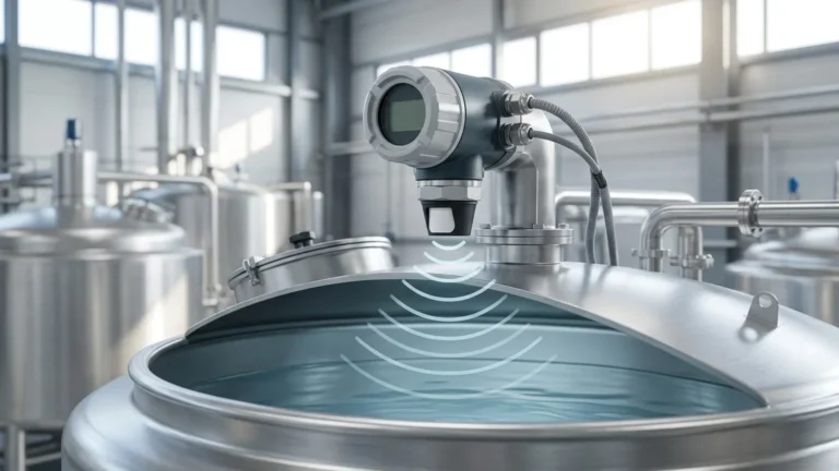
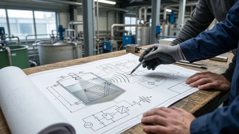
An ultrasonic transducer, typically made of piezoelectric crystals, emits a high-frequency acoustic pulse. This pulse travels through the air or gas space above the medium, reflects off the surface of the material, and returns to the transducer. The electronics within the meter measure the total time elapsed from the emission of the pulse to the reception of the echo.
The distance between the sensor and the material surface is calculated using the formula:
D = (c × t) / 2
Where:
* D is the distance to the surface.
* c is the speed of sound in the medium (typically air).
* t is the total travel time (round trip).
Because the installation height (H) of the sensor is known, the actual level (L) of the material is determined by subtracting the measured distance from the total height: L = H – D.
The Role of Temperature Compensation
The speed of sound is not constant; it fluctuates based on the temperature of the air through which it travels. In air, the speed of sound changes by approximately 0.17% for every degree Celsius change. To maintain accuracy, modern Ultrasonic Level Meters include integrated temperature sensors to automatically compensate for these variations in the vessel headspace.
Key Components of a Ultrasonic System
A standard system generally consists of three primary elements:
1. The Transducer: The "eyes and ears" of the device, responsible for converting electrical energy into mechanical vibrations (sound) and vice versa.
2. The Signal Processor: Advanced microprocessors that filter out noise, manage false echoes from internal tank obstructions (like agitators or ladders), and convert the time-of-flight data into a standardized output signal.
3. The Housing: Typically constructed from materials like PP (Polypropylene), PVDF (Polyvinylidene Fluoride), or stainless steel to withstand corrosive environments.
Selection Criteria: Choosing the Right Meter
Selecting a ultrasonic level sensor requires a detailed analysis of the application environment. Engineers should evaluate the following parameters:
1. Measurement Range
Each sensor has a minimum and maximum range. The "Dead Zone" or "Blanking Distance" is the area immediately below the transducer where measurements cannot be taken because the transducer is still vibrating from the pulse emission and cannot yet receive an echo. Typical dead zones range from 0.2m to 0.5m (approx. 8 to 20 inches).
2. Material Characteristics
* Liquids: Generally provide a strong, flat reflective surface. However, heavy foam can absorb the acoustic signal, leading to signal loss.
* Solids: Powders and granules often have an angle of repose, which can scatter the sound waves. For solids, sensors with higher power and narrower beam angles are usually required.
3. Environmental Conditions
* Pressure: Ultrasonic meters are typically designed for atmospheric or near-atmospheric pressure. High pressure increases the density of the air, which can affect sound propagation and sensor seal integrity.
* Vapor and Dust: Heavy steam or dense dust can attenuate the sound pulse. In such cases, a higher-frequency sensor or a transition to radar technology may be necessary.
Selection Comparison Table
| Feature | Compact/Integrated Meter | Remote/Split-Type Meter |
| :— | :— | :— |
| Installation | Single unit mounted on tank top | Sensor on tank; display mounted remotely |
| Ease of Use | Simple wiring, lower cost | Easier to read in restricted access areas |
| Environment | Suitable for standard industrial areas | Ideal for hazardous or high-vibration zones |
| Output Options | 4-20mA, HART, RS485 | 4-20mA, Relays, RS485, Modbus |
| Typical Range | 0.4m to 15m | 0.4m to 30m+ |
Installation Considerations and Best Practices
Correct installation is the most critical factor in ensuring the long-term reliability of a ultrasonic level measurement system. Even the most advanced meter will fail if positioned incorrectly.
Positioning the Sensor
* Avoid the Center: In cylindrical tanks with domed tops, mounting the sensor in the exact center can cause multiple reflections to converge, creating a "parabolic effect" that confuses the signal processor.
* Stay Away from Inlets: Do not install the sensor directly above the fill stream. The falling material will obstruct the ultrasonic pulse and cause erratic readings.
* Perpendicular Alignment: The transducer face must be perfectly parallel to the liquid surface. A tilt of even a few degrees can cause the echo to bounce away from the transducer rather than back to it.
Managing the Beam Angle
The ultrasonic pulse spreads out like a cone. This is known as the beam angle (typically between 5° and 12°). Ensure that no internal obstructions, such as pipes, reinforcement beams, or cooling coils, enter this cone. If an obstruction is unavoidable, many Welk instruments offer "False Echo Suppression," allowing the software to ignore specific static reflections.
Metric Units and Accuracy Standards
In global industrial applications, accuracy is usually defined as a percentage of the measured span or a fixed millimeter value (e.g., ±0.25% of range or ±3mm). For a tank with a 10-meter depth, a high-quality ultrasonic meter should provide precision within ±25mm under stable conditions.
Limitations and When to Consider Alternatives
While a ultrasonic level meter is a robust tool, it is not a universal solution. Engineers should be aware of the following limitations:
1. Vacuum Conditions: Sound cannot travel in a vacuum. If a process vessel operates under a full vacuum, ultrasonic technology will not function.
2. High Temperature: Most ultrasonic transducers are limited to temperatures below 80°C (176°F). Beyond this, the piezoelectric elements can degrade, and the speed-of-sound calculations become highly unreliable due to temperature gradients.
3. Heavy Foam: As mentioned, foam acts as an acoustic insulator. If the foam is thick and dense, the pulse may never return to the sensor. In these scenarios, a Hydrostatic Level Transmitter or a Guided Wave Radar (GWR) is often preferred.
Common Applications
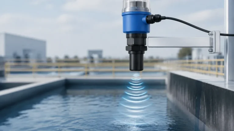
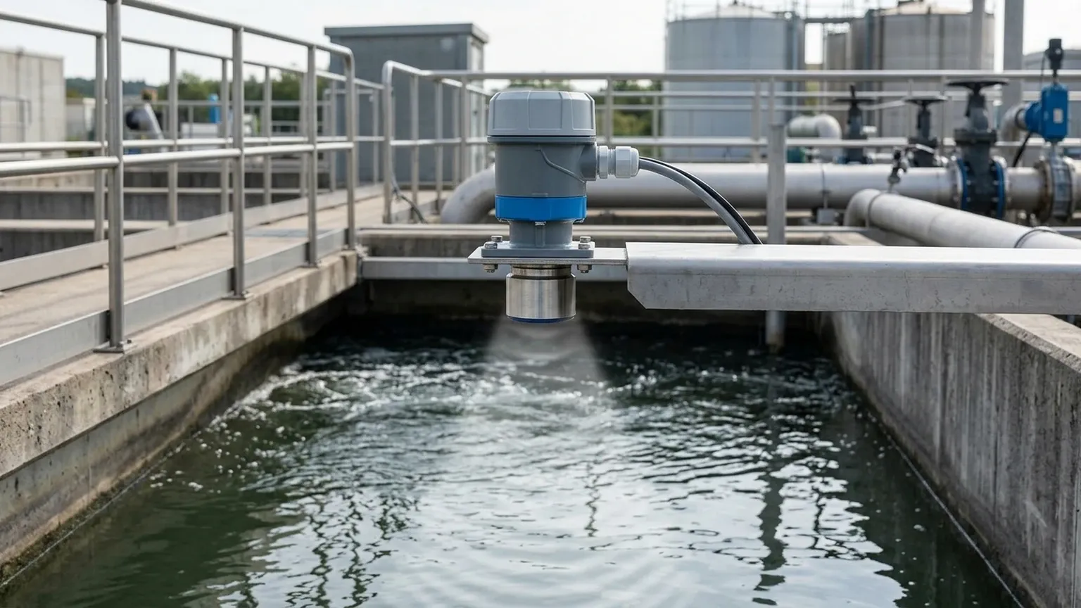
* Water and Wastewater Treatment: Monitoring levels in open channels, flumes, weirs, and wet wells. The non-contact nature prevents sensor fouling from raw sewage.
* Chemical Processing: Measuring corrosive acids or bases in plastic storage tanks where contact-based sensors would corrode.
* Food and Beverage: Monitoring ingredient silos or water storage where hygiene is paramount; the non-contact sensor avoids contamination risks.
* Industrial Automation: Sump pit monitoring and cooling tower water management.
Frequently Asked Questions (FAQ)
Q: Can I use a ultrasonic level meter for solids like grain or sand?
A: Yes, but with caveats. You must select a sensor specifically designed for solids, which usually features a higher power output and a dust-resistant transducer face. The maximum effective range is typically reduced by 50% compared to liquids due to the uneven reflective surface.
Q: How does wind affect outdoor ultrasonic measurements?
A: Strong crosswinds can "blow" the acoustic pulse away from the transducer, especially over long distances. For outdoor sumps or lagoons, a protective stilling well or a sensor with a narrower beam angle can help mitigate this effect.
Q: What is the maintenance requirement for these meters?
A: Because there are no moving parts and the sensor does not touch the medium, maintenance is minimal. Periodically check the transducer face for condensation or dust buildup and wipe it with a soft cloth if necessary.
Q: How do I handle tanks with heavy agitation?
A: Agitation creates surface turbulence, which can scatter the echo. Using a stilling well (a vertical pipe that stabilizes the liquid surface) allows the ultrasonic pulse to provide a steady reading despite the turbulence in the main tank.
Conclusion
Implementing a ultrasonic level measurement system offers a balance of accuracy, ease of installation, and cost-effectiveness. By understanding the acoustic properties of the application and following rigorous installation guidelines, industrial operators can achieve reliable level monitoring that enhances both safety and efficiency. For specific project requirements or customized OEM solutions, consulting with a specialized manufacturer like Welk ensures that the selected instrument is perfectly matched to the operational environment.