Ultrasonic Level Sensor Drawing
Understanding the Ultrasonic Level Sensor Drawing for Industrial Applications
In the field of industrial process control, precision begins long before a device is powered on. For engineers and system integrators, the technical documentation—specifically the ultrasonic level sensor drawing—serves as the foundational blueprint for successful integration. These drawings provide the critical spatial and mechanical data required to ensure that Ultrasonic Level Meters perform accurately within the constraints of tanks, silos, and open channels.
As a professional manufacturer, Welk emphasizes the importance of verifying mechanical dimensions, beam angles, and mounting requirements during the design phase. This guide explores the technical components of ultrasonic level measurement, the specifics of sensor drawings, and the practical considerations for selecting and installing these instruments.
Measurement Principle of Ultrasonic Level Meters
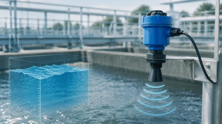
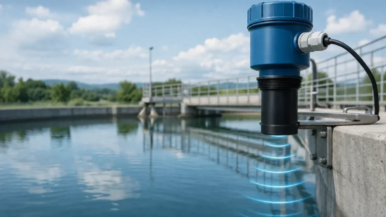
Before analyzing a technical drawing, it is essential to understand the physics governing the device. Ultrasonic level meters operate on the "Time-of-Flight" (ToF) principle. The sensor’s transducer emits a high-frequency acoustic pulse that travels through the air toward the medium surface. When the pulse hits the surface, it reflects back as an echo to the transducer.
The instrument calculates the distance based on the formula:
Distance = (Speed of Sound × Time) / 2
Because the speed of sound is influenced by air temperature, modern ultrasonic sensors include a built-in temperature probe to compensate for variations, ensuring accuracy remains within 0.25% to 0.5% of the measured range. The resulting distance is then subtracted from the total tank height (programmed into the meter) to determine the liquid level.
Key Components of an Ultrasonic Level Sensor Drawing
An engineering drawing for an ultrasonic sensor is more than a simple diagram; it is a specification sheet that dictates how the unit will interface with the physical environment. When reviewing an ultrasonic level sensor drawing, engineers must focus on several key areas:
1. Mechanical Dimensions and Mounting Interfaces
The drawing specifies the housing diameter and the type of process connection. Common connections include:
* Threaded Connections: Often G2" or 1.5" NPT, suitable for smaller tanks or bracket mounting.
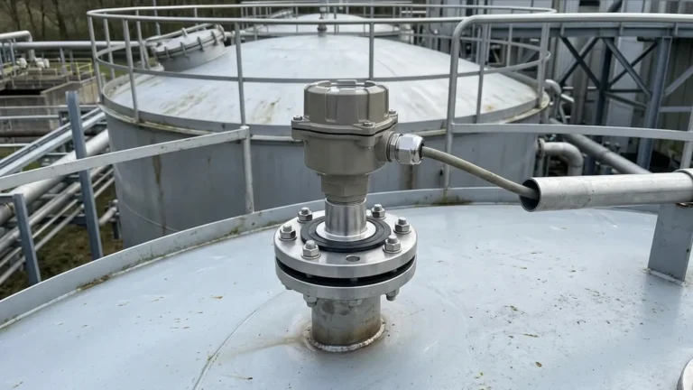
* Flange Connections: Standard DN50, DN80, or DN100 flanges for pressurized or heavy-duty industrial tanks.
* Housing Height: The total vertical space required above the mounting point, which is crucial for installations with limited overhead clearance.
2. The Blocking Distance (Dead Zone)
Every ultrasonic sensor has a "dead zone" or blocking distance—a region immediately below the transducer face where measurements cannot be taken. This occurs because the transducer cannot receive an echo while it is still vibrating from the transmission of the pulse. In a technical drawing, this is typically marked as a shaded area. For a sensor with a 5-meter range, the dead zone is often between 0.25m and 0.4m.
3. Beam Angle and Emission Cone
The drawing will indicate the beam angle (typically ranging from 5° to 12°). This defines the conical path the sound wave travels. It is vital to ensure that no internal tank obstructions, such as ladders, agitators, or weld seams, enter this cone, as they will cause false echoes.
4. Electrical and Wiring Layouts
For system integration, the drawing includes the wiring terminal diagram. This specifies whether the unit is a 2-wire (loop-powered) or 4-wire system and identifies the terminals for 4-20mA output, RS485 Modbus communication, and relay outputs for high/low alarms.
Technical Selection Table
Choosing the right model requires balancing range requirements with the physical constraints identified in the sensor drawing. Below is a general selection guide for standard industrial applications.
| Feature | Short Range Model | Standard Range Model | Extended Range Model |
| :— | :— | :— | :— |
| Measurement Range | 0.3m – 5m | 0.4m – 10m | 0.6m – 15m |
| Dead Zone | ≤ 0.3m | ≤ 0.4m | ≤ 0.6m |
| Beam Angle | 8° – 10° | 10° – 12° | 12° |
| Process Connection | G2" Thread | DN80 Flange | DN100 Flange |
| Output Signal | 4-20mA / RS485 | 4-20mA / RS485 | 4-20mA / RS485 |
| Power Supply | 24V DC | 24V DC / 220V AC | 24V DC / 220V AC |
Installation Considerations and Best Practices
Proper installation is the most critical factor in the reliability of ultrasonic level meters. Even the highest quality sensor will fail if the physical placement contradicts the requirements shown in the ultrasonic level sensor drawing.
Distance from the Tank Wall
The sensor should not be mounted too close to the tank wall. A general rule of thumb is to maintain a distance of at least 1/6th of the tank height from the wall to avoid interference from wall reflections. For a 6-meter tank, the sensor should be at least 1 meter away from the side.
Avoiding Obstructions
The emission cone must remain clear. If an agitator or a ladder is located within the beam path, the sensor may lock onto the obstruction rather than the liquid level. In cases where obstructions are unavoidable, advanced meters offer "False Echo Suppression" software to ignore specific static reflections.
Perpendicular Alignment
The transducer face must be perfectly parallel to the liquid surface. If the sensor is tilted, the pulse will reflect away from the transducer, resulting in a "Loss of Echo" (LOE) error. In tanks with domed tops, a flange or aiming device may be necessary to ensure vertical alignment.
Environmental Factors
* Foam: Heavy surface foam absorbs ultrasonic signals. If foam is present, a radar level meter or a stilling well may be required.
* Vapor and Steam: High concentrations of steam can change the speed of sound or attenuate the signal. In these environments, ensure the sensor is rated for high humidity.
* Vacuum: Ultrasonic waves require a medium (air/gas) to travel. They cannot function in a vacuum.

Limitations of Ultrasonic Technology
While highly versatile and cost-effective, ultrasonic level meters have specific factual boundaries:
1. Pressure Limits: Most standard ultrasonic sensors are designed for atmospheric pressure or very low-pressure environments (typically < 0.3 MPa). High pressure significantly alters the density of the air, affecting sound propagation.
2. Temperature Extremes: Standard units usually operate between -20°C and +60°C. For temperatures exceeding this range, the transducer materials and the accuracy of temperature compensation may be compromised.
3. Dust and Solids: While used in some solids applications, heavy dust can attenuate the signal. For fine powders or very uneven surfaces, the effective range is often reduced by 50% or more.
Frequently Asked Questions (FAQ)
Q: Can I cut the cable of my ultrasonic level sensor if it is too long?
A: For most 4-wire or RS485 models, the cable can be shortened. However, for some specialized integrated models where the cable is part of a calibrated circuit, cutting it may affect performance. Always consult the specific wiring drawing before modifying factory cables.
Q: How do I handle a tank with a very small mounting nozzle?
A: If the nozzle is long and narrow, it can create "ringing" interference. The ultrasonic level sensor drawing will usually specify a maximum nozzle length-to-diameter ratio. Ideally, the transducer should extend slightly past the bottom of the nozzle into the tank.
Q: What is the difference between an integrated and a remote ultrasonic level meter?
A: An integrated meter has the sensor and the display/electronics in a single housing. A remote version (split-type) separates the sensor head from the controller, allowing the display to be mounted at eye level or in a control room while the sensor is at the top of a tall tank.
Conclusion for Project Planning
When integrating level measurement into an industrial project, the ultrasonic level sensor drawing is the primary reference point for mechanical and electrical compatibility. By understanding the measurement principles and respecting the physical limitations of the technology—such as the dead zone and beam angle—engineers can ensure long-term reliability and accuracy. For applications involving water treatment, chemical storage, or general industrial automation, Ultrasonic Level Meters remain one of the most reliable and cost-effective non-contact solutions available.
Before finalizing your design, confirm the specific CAD dimensions and mounting requirements with your equipment provider to ensure a seamless installation process.