Water Tank Level Sensor Controller
Water Tank Level Sensor Controller
In industrial water management, the integration of a water tank level sensor controller is fundamental to maintaining operational efficiency, preventing pump cavitation, and avoiding costly overflows. These systems serve as the bridge between raw physical measurement and automated process control. A complete system typically consists of a sensing element—such as an ultrasonic transducer, a radar transmitter, or a hydrostatic probe—and a digital controller that interprets signals to manage pumps, valves, and alarms.
Selecting the appropriate technology requires a deep understanding of the measurement principles involved, the physical characteristics of the liquid, and the specific requirements of the storage environment.
Measurement Principles for Water Tank Level Sensing
Before selecting a water tank level sensor controller, it is essential to understand how different sensing technologies interact with the medium. Each principle offers distinct advantages depending on the tank geometry and environmental conditions.
Ultrasonic Level Measurement (Non-Contact)
Ultrasonic sensors operate on the Time-of-Flight (ToF) principle. The sensor emits high-frequency sound pulses (typically between 20 kHz and 200 kHz) toward the water surface. These waves reflect off the surface and return to the transducer. The controller calculates the distance based on the speed of sound in air using the formula:
Distance = (Speed of Sound × Time) / 2
Because the speed of sound is temperature-dependent, most industrial ultrasonic sensors include an integrated temperature probe to compensate for fluctuations. This technology is ideal for standard water storage but can be affected by heavy foam, steam, or extreme turbulence.
Radar Level Measurement (Non-Contact)
Radar sensors also use the ToF principle but utilize electromagnetic waves (microwaves) rather than sound. High-frequency signals (often 26GHz or 80GHz) are emitted and reflected. Unlike ultrasonic waves, radar signals are virtually unaffected by air temperature, pressure, vacuum, or the presence of vapors and dust. This makes radar a superior choice for high-precision applications or tanks where steam is present.
Hydrostatic Level Measurement (Contact)
Hydrostatic sensors, or submersible pressure transmitters, measure the level based on the liquid column's weight. The pressure at the bottom of a tank is directly proportional to the height of the liquid, calculated by:
P = ρ × g × h
Where *P* is pressure, *ρ* (rho) is the density of the liquid, *g* is gravity, and *h* is the height of the liquid. These sensors are robust and highly effective for deep tanks or reservoirs where top-mounting a non-contact sensor is impractical. However, they require the liquid density to remain relatively constant for accurate readings.
Magnetic and Float-Based Measurement
Magnetic level gauges and float switches use buoyancy. A float containing a magnet moves with the water level along a stem or chamber. In a continuous measurement setup, this magnet triggers reed switches or a magnetostrictive sensor to provide a level reading. These are purely mechanical at the sensing point, making them reliable for simple pump-up/pump-down logic.
The Role of the Level Controller
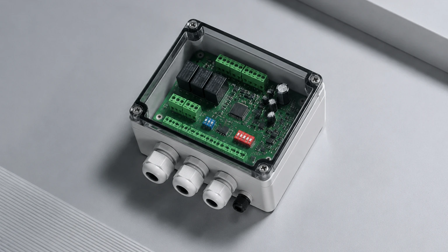
The water tank level sensor controller is the intelligence of the system. While the sensor provides the data, the controller performs the logic. Most industrial controllers accept a 4-20mA or RS485 Modbus signal from the sensor and provide the following functions:
1. Signal Conversion: Translating the current or digital signal into a readable format (e.g., meters, millimeters, or percentage of volume).
2. Relay Logic: Providing programmable dry contacts to start or stop pumps at specific setpoints. For example, a controller might trigger a fill pump when the tank hits 20% and stop it at 90%.
3. Alarm Management: Activating audible or visual alerts for High-High (overflow risk) or Low-Low (dry run protection) conditions.
4. Data Retransmission: Sending a secondary 4-20mA or digital signal to a centralized PLC (Programmable Logic Controller) or SCADA system for plant-wide monitoring.
Technology Selection Matrix
Choosing the right water tank level sensor controller system involves balancing accuracy, installation constraints, and budget. The following table provides a comparison of common industrial technologies.
| Technology | Accuracy | Mounting | Media Suitability | Typical Application |
| :— | :— | :— | :— | :— |
| Ultrasonic | ±0.25% to 0.5% | Top-mounted | Clean water, wastewater | Municipal water tanks, chemical storage |
| Radar | ±1mm to 3mm | Top-mounted | All liquids, steam, foam | High-precision process tanks, volatile liquids |
| Hydrostatic | ±0.1% to 0.5% | Submerged/Bottom | Clear water, greywater | Deep wells, reservoirs, vented tanks |
| Magnetic Gauge | ±5mm to 10mm | Side-mounted | Clean liquids | Boiler feed tanks, high-pressure vessels |
| Float Switch | Point level only | Top/Side | Most liquids | Simple sump pump control, overflow backup |
Installation and Engineering Considerations
Proper installation is as critical as selecting the right sensor. Failure to account for tank internal structures or environmental factors can lead to signal loss or false readings.
Dead Zones and Blocking Distances
Non-contact sensors (ultrasonic and radar) have a "dead zone" or "blocking distance" immediately below the transducer face where measurements cannot be taken. For ultrasonic sensors, this is typically 0.25m to 0.6m depending on the range. If the water level rises into this zone, the sensor may report an error or an incorrect "full" reading. Engineers must ensure the sensor is mounted high enough above the maximum fill line.
Obstruction Avoidance
In tanks with internal ladders, heating coils, or agitators, sensors must be positioned to avoid signal interference. For ultrasonic sensors, the beam spreads in a cone shape (typically 5° to 12°). If the beam hits a ladder, it will return a false high-level reading. Radar sensors with 80GHz technology offer narrower beams, which are easier to install in cluttered tanks.
Stilling Wells and Bypass Chambers
If the water surface is extremely turbulent due to high-flow inlets or mixers, a stilling well (a vertical pipe submerged in the liquid) can be used. The sensor is mounted at the top of the pipe, which provides a calm surface for measurement. This is a common practice in industrial wastewater treatment.
Cable Protection for Hydrostatic Probes
When using hydrostatic sensors, the vent tube in the cable (which compensates for atmospheric pressure changes) must remain unobstructed and protected from moisture. Using a specialized junction box with a desiccant filter is recommended to prevent condensation from entering the vent tube and damaging the internal electronics.
Operational Limitations and Environmental Factors
While modern water tank level sensor controller systems are highly resilient, certain factors can limit their performance:
* Temperature Extremes: Rapid temperature changes can shift the speed of sound, affecting ultrasonic accuracy. In outdoor tanks exposed to direct sunlight, sunshields should be used to prevent the sensor body from overheating.
* Chemical Compatibility: For tanks containing treated water or chemicals (such as chlorine or acids), the wetted materials of the sensor (PVDF, PTFE, or Stainless Steel) must be verified for chemical resistance.
* Vacuum or Pressure: Standard ultrasonic sensors are designed for atmospheric pressure. In pressurized tanks, radar or hydrostatic sensors are required.
* Foam and Vapor: Heavy surface foam can absorb ultrasonic pulses, leading to signal loss. Radar is generally more effective in these conditions, though high-density foam may still require a guided wave radar (GWR) solution.
Frequently Asked Questions (FAQ)
Q: Can one controller manage multiple tanks?
A: Yes, multi-channel controllers are available that can accept inputs from 2 to 8 different sensors simultaneously, providing independent relay outputs for each tank.
Q: How do I calibrate a hydrostatic sensor for different liquids?
A: Since hydrostatic sensors measure pressure, they are calibrated based on the specific gravity (SG) of the liquid. If the liquid is heavier than water (SG > 1.0), the sensor will report a higher level than actual unless the controller is adjusted for the correct density.
Q: What is the maximum distance between the sensor and the controller?
A: For a standard 4-20mA analog signal, the distance can typically reach up to 1,000 meters depending on the cable quality and electromagnetic interference. For RS485 Modbus, distances of 1,200 meters are common.
Q: Is it necessary to have a secondary backup sensor?
A: In critical applications, such as fire water tanks or high-value chemical storage, it is best practice to install a secondary mechanical float switch as a redundant High-High alarm to prevent overflows in the event of an electronic failure.
Conclusion
A robust water tank level sensor controller system is essential for modern industrial automation. By understanding the physics of measurement—whether it be the acoustic reflections of ultrasonic waves, the electromagnetic precision of radar, or the pressure-based logic of hydrostatic probes—engineers can select a system that ensures long-term reliability. For a comprehensive range of industrial instrumentation, engineers can visit the Main Page to review product options and application support.
When specifying a system, always confirm the tank height, the presence of internal obstructions, the chemical nature of the water, and the required control outputs to ensure the selected hardware meets the project's operational demands.