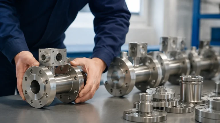
Blending System Flow Sensor
Blending System Flow Sensor
In industrial process engineering, blending is the precise combination of two or more fluid streams to create a final product with specific properties. Whether in chemical processing, food and beverage production, or petrochemical refining, the accuracy of this process depends entirely on the performance of the blending system flow sensor. This instrument is responsible for monitoring the rate of delivery for each component, ensuring that the ratio remains within strict tolerances to prevent off-specification batches and material waste.
Selecting the correct flow sensor for a blending system requires a deep understanding of fluid dynamics, measurement principles, and the specific requirements of the application. This guide explores the technical foundations of flow measurement in blending environments, selection criteria, and engineering best practices for installation and maintenance.
Understanding Blending Systems and Flow Dynamics
Blending systems generally fall into two categories: batch blending and continuous (in-line) blending. In batch blending, components are sequentially or simultaneously added to a vessel until the desired volume or weight is reached. In continuous blending, all components are metered into a common header at controlled rates, maintaining a constant ratio in real-time.
In both scenarios, the blending system flow sensor must provide high repeatability and fast response times. Because blending often involves fluids with varying viscosities, temperatures, and chemical compositions, the sensor must be resilient to these changes while maintaining its calibrated accuracy. For a broader overview of instrumentation used in these processes, including level and flow integration, engineers can refer to the Main Page for technical specifications.
Core Measurement Principles for Blending Applications
There is no single "best" sensor for every blending application. Instead, engineers must choose from several measurement principles based on the physical properties of the fluids being mixed.
Coriolis Mass Flow Meters
Coriolis meters are often considered the gold standard for blending because they measure mass flow directly rather than volume. The principle relies on the Coriolis effect: a fluid moving through a vibrating tube induces a phase shift in the vibration proportional to the mass flow rate.
* Advantages: High accuracy (often ±0.1% or better), measures density and temperature simultaneously, and is independent of viscosity and flow profile.
* Applications: High-value chemicals, oils, and food ingredients where mass-based ratios are critical.
Electromagnetic Flow Meters (Magmeters)
Magmeters operate on Faraday’s Law of Electromagnetic Induction. As a conductive fluid passes through a magnetic field, it generates a voltage proportional to its velocity. This voltage is captured by electrodes mounted in the flow tube.
* Advantages: No moving parts, zero pressure drop, and highly resistant to corrosive fluids.
* Limitations: The fluid must be electrically conductive (typically >5 μS/cm). They cannot measure oils or deionized water.
Ultrasonic Flow Meters (Transit-Time)
Transit-time ultrasonic sensors use pairs of transducers to send sound waves through the fluid. The difference in time between the upstream and downstream signals is used to calculate the flow velocity.
* Advantages: Non-invasive (clamp-on versions available), no pressure drop, and suitable for large pipe diameters.
* Applications: Water treatment blending and retrofitting existing systems where pipe cutting is not feasible.
Turbine Flow Meters
Turbine meters utilize a multi-bladed rotor suspended in the fluid stream. The fluid's velocity causes the rotor to spin, and a pickup sensor counts the pulses generated by the rotor blades.
* Advantages: Excellent repeatability and fast response times, making them ideal for high-speed batching.
* Limitations: Sensitive to viscosity changes and prone to wear if the fluid contains abrasive solids.
Selection Criteria for a Blending System Flow Sensor
When evaluating a blending system flow sensor, several technical parameters must be prioritized to ensure long-term reliability.
1. Accuracy and Repeatability
In blending, repeatability is often more important than absolute accuracy. Repeatability ensures that the sensor provides the same reading for the same flow rate every time, allowing the control system to maintain a consistent ratio across different production runs.
2. Turndown Ratio
The turndown ratio (or rangeability) defines the range over which the sensor maintains its specified accuracy. If a blending process requires a wide range of flow rates (e.g., 10 L/min to 500 L/min), a sensor with a high turndown ratio, such as a Coriolis or high-end Magmeter, is necessary.
3. Fluid Compatibility and Viscosity
Viscosity can significantly impact the Reynolds number of the flow, affecting the accuracy of velocity-based sensors like turbines or vortex meters. For high-viscosity fluids like syrups or heavy oils, Coriolis meters are typically preferred. Additionally, the wetted materials of the sensor (e.g., 316L stainless steel, Hastelloy, or PTFE lining) must be chemically compatible with the process media.
4. Response Time
In automated blending systems, the flow sensor must communicate with a PLC (Programmable Logic Controller) or DCS (Distributed Control System). A sensor with a slow response time can lead to "overshoot" in batching, where the valve closes too late, resulting in an incorrect mixture.
Installation Considerations and Engineering Best Practices
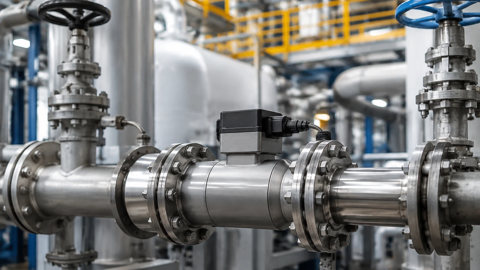
Proper installation is critical to the performance of any blending system flow sensor. Even the most expensive meter will fail to provide accurate data if installed incorrectly.
* Straight Pipe Runs: Most velocity-based sensors require a specific length of straight pipe upstream (typically 5 to 10 diameters) and downstream (3 to 5 diameters) to eliminate turbulence and stabilize the flow profile. If space is limited, flow conditioners may be required.
* Orientation: For liquid applications, the sensor should be installed in a position where the pipe is always full. Vertical upward flow is often preferred to prevent air entrapment. Horizontal installations should avoid placing electrodes at the top or bottom of the pipe (in magmeters) to prevent interference from air bubbles or sediment.
* Grounding: Electromagnetic flow meters require proper electrical grounding to the fluid to eliminate stray currents that can cause signal noise.
* Vibration Control: Coriolis meters are sensitive to external mechanical vibrations. They should be mounted on stable supports and isolated from pumps or vibrating machinery using flexible couplings if necessary.
Limitations and Common Operational Risks
Engineers must be aware of the inherent limitations of flow sensing technology to mitigate risks during the design phase.
1. Entrained Air: Most flow sensors struggle with two-phase flow (liquid and gas). Air bubbles can cause significant measurement errors or signal loss. Air eliminators should be installed upstream of the blending system flow sensor if the fluid source is prone to aeration.
2. Pressure Drop: Sensors like turbine meters or differential pressure plates introduce a pressure drop into the system. This must be accounted for in pump sizing to ensure the system can maintain the required flow rates.
3. Pulsating Flow: Positive displacement pumps or certain diaphragm pumps create pulsating flow. This can confuse sensors with slow sampling rates. Damping devices or specific signal processing filters may be needed to achieve a steady reading.
Comparative Analysis of Flow Sensor Technologies
The following table summarizes the suitability of common sensors for blending applications:
| Sensor Type | Accuracy (Typical) | Turndown Ratio | Fluid Compatibility | Maintenance Requirement |
| :— | :— | :— | :— | :— |
| Coriolis | ±0.1% | 100:1 | Universal (Mass-based) | Low (No moving parts) |
| Electromagnetic | ±0.25% – 0.5% | 20:1 – 50:1 | Conductive liquids only | Low |
| Turbine | ±0.25% – 0.5% | 10:1 – 15:1 | Clean, low-viscosity | High (Bearings wear) |
| Ultrasonic | ±0.5% – 1.0% | 20:1 | Most clean liquids | Low |
| Thermal Mass | ±1.0% | 10:1 | Gases/Specific liquids | Medium |
Maintenance and Calibration
To maintain the integrity of a blending system, regular calibration is mandatory. In many industries, such as pharmaceuticals or petrochemicals, flow sensors must be calibrated annually against a traceable standard.
Field verification can be performed using a "master meter" or by conducting a draw-down test where a known volume is pumped into a calibrated vessel. If the sensor shows a drift in accuracy, it may indicate coating on the electrodes, wear on internal components, or changes in the fluid's properties that were not accounted for in the initial setup.
Frequently Asked Questions (FAQ)
Q: Can a blending system flow sensor handle multiple different fluids in the same line?
A: This depends on the technology. A Coriolis meter can handle different fluids easily because it measures mass. However, a turbine meter or ultrasonic meter may need to be recalibrated if the viscosity or speed of sound of the fluid changes significantly.
Q: How do I handle blending for very small flow rates?
A: For micro-blending or additive injection, specialized micro-Coriolis or gear-type positive displacement meters are used, as standard industrial meters may not have the sensitivity required for very low velocities.
Q: What is the impact of temperature on flow measurement?
A: Temperature affects fluid density and viscosity. If using a volumetric meter (like a turbine or magmeter), a temperature sensor should be used in conjunction with the flow sensor to calculate the compensated mass flow, ensuring the blend ratio remains accurate regardless of thermal expansion.
Q: Is it necessary to install a filter before the flow sensor?
A: For turbine and positive displacement meters, a strainer or filter is essential to prevent solids from damaging the internal moving parts. For magmeters and Coriolis meters, it is less critical but still recommended if large debris is expected in the process stream.
By carefully matching the blending system flow sensor to the specific chemical and physical parameters of the process, engineers can ensure high-quality output and operational efficiency. For more information on industrial measurement solutions, visit the Main Page to explore our full range of instrumentation.