Flare Flow Meter
Flare Flow Meter
In industrial process environments, flare systems serve as the final line of defense for pressure relief and emergency gas disposal. Accurate measurement of the gases sent to these flares is a critical requirement for environmental compliance, loss control, and safety management. A flare flow meter must operate under some of the most challenging conditions found in any industrial plant, including extremely wide flow ranges, varying gas compositions, and high-velocity discharge events.
This guide provides a technical overview of flare flow measurement technologies, selection criteria, and the integration of these systems within broader process safety frameworks. For engineers seeking comprehensive instrumentation for associated process vessels, such as knockout drums, reviewing the Main Page of specialized manufacturers can provide insights into the level measurement technologies required to support flare system integrity.
Measurement Principles for Flare Gas
Flare gas measurement is unique because the flow can vary from a low-velocity sweep gas (to prevent atmospheric air ingress) to near-sonic velocities during an emergency blowdown. Three primary technologies are typically employed for this application.
1. Ultrasonic Transit-Time Flow Meters
Ultrasonic technology is the industry standard for flare gas applications. It operates on the principle of transit-time difference. Two transducers are mounted on the pipe, typically in a diagonal arrangement. One acts as a transmitter and the other as a receiver, then they switch roles.
When gas is flowing, the pulse traveling with the flow (downstream) moves faster than the pulse traveling against the flow (upstream). The difference in these transit times is directly proportional to the flow velocity. Because sound speed is also measured, these meters can calculate the average molecular weight of the gas, which is vital for converting actual volume to mass flow when gas composition varies.
2. Thermal Mass Flow Meters
Thermal mass flow meters utilize the heat transfer properties of the gas. They typically consist of two sensors: a velocity sensor and a temperature sensor. The velocity sensor is heated to a specific temperature above the ambient gas temperature. As gas flows past the sensor, it carries heat away. The amount of electrical power required to maintain the temperature differential is proportional to the mass flow rate.
While highly sensitive to low-flow conditions, thermal mass meters are sensitive to changes in the specific heat of the gas. In flare systems where the gas composition changes frequently (e.g., switching from methane to heavier hydrocarbons), these meters require real-time compensation or may suffer from significant accuracy errors.
3. Differential Pressure (DP) Meters
DP meters, such as Averaging Pitot Tubes or specialized Orifice plates, measure the pressure drop across a restriction. While robust and well-understood, they generally lack the turndown ratio required for flare applications. They are often used as secondary or redundant systems in specific stable-composition vent lines rather than main flare headers.
Key Evaluation Criteria for Selection
Selecting a flare flow meter requires a deep understanding of the process dynamics. The following factors are decisive in engineering a reliable measurement solution.
Turndown Ratio
Turndown ratio is the ratio between the maximum and minimum measurable flow rates. Flare systems require an immense turndown, often exceeding 1000:1. A meter must be able to detect a leak in a valve (low velocity, approx. 0.03 m/s or 0.1 ft/s) and also measure a full plant emergency blowdown (high velocity, up to 100 m/s or 328 ft/s).
Gas Composition and Molecular Weight
Flare gas is rarely a single component. It is a mixture of hydrocarbons, hydrogen, nitrogen, and sometimes corrosive gases like H2S. Ultrasonic meters are preferred here because they can use the measured speed of sound to estimate the molecular weight, allowing for more accurate mass flow calculations without requiring a continuous gas chromatograph feed.
Pressure and Temperature Extremes
Flare headers usually operate at low pressures, but the temperature can swing from cryogenic (in LNG applications) to several hundred degrees Celsius during a hot gas release. The meter must be rated for these extremes and provide temperature compensation.
Selection Table for Flare Flow Technologies
| Feature | Ultrasonic (Transit-Time) | Thermal Mass | Differential Pressure |
| :— | :— | :— | :— |
| Turndown Ratio | Excellent (up to 4000:1) | Good (up to 100:1) | Poor (typically 5:1 to 10:1) |
| Accuracy | High (±1% to 3%) | Moderate (±2% to 5%) | Moderate |
| Pressure Drop | Zero (Non-intrusive) | Negligible | Significant |
| Composition Sensitivity | Low (Calculates MW) | High | Moderate |
| Maintenance | Low (No moving parts) | Moderate (Sensor fouling) | High (Impulse line plugging) |
| Initial Cost | High | Moderate | Low to Moderate |
Installation and Engineering Considerations
Proper installation is as important as the technology itself. Because flare lines are often large-diameter pipes, the following engineering steps are mandatory:
1. Straight Run Requirements: To ensure a fully developed flow profile, ultrasonic meters typically require 20 diameters (20D) of straight pipe upstream and 10 diameters (10D) downstream. If these distances are unavailable, flow conditioners or multi-path ultrasonic meters may be required.
2. Transducer Orientation: In horizontal pipes, transducers should be mounted in the 3 o'clock and 9 o'clock positions to avoid signal interference from liquid pooling at the bottom or gas pockets/debris at the top.
3. Hot Tapping: For existing flare lines that cannot be shut down, "hot tapping" allows for the installation of insertion-style transducers while the system is pressurized. This requires specialized equipment and strict safety protocols.
4. Hazardous Area Ratings: All electronics must meet local explosion-proof or intrinsic safety standards (e.g., ATEX, IECEx, or Class I Div 1) due to the presence of flammable gases.
The Role of Level Measurement in Flare Systems
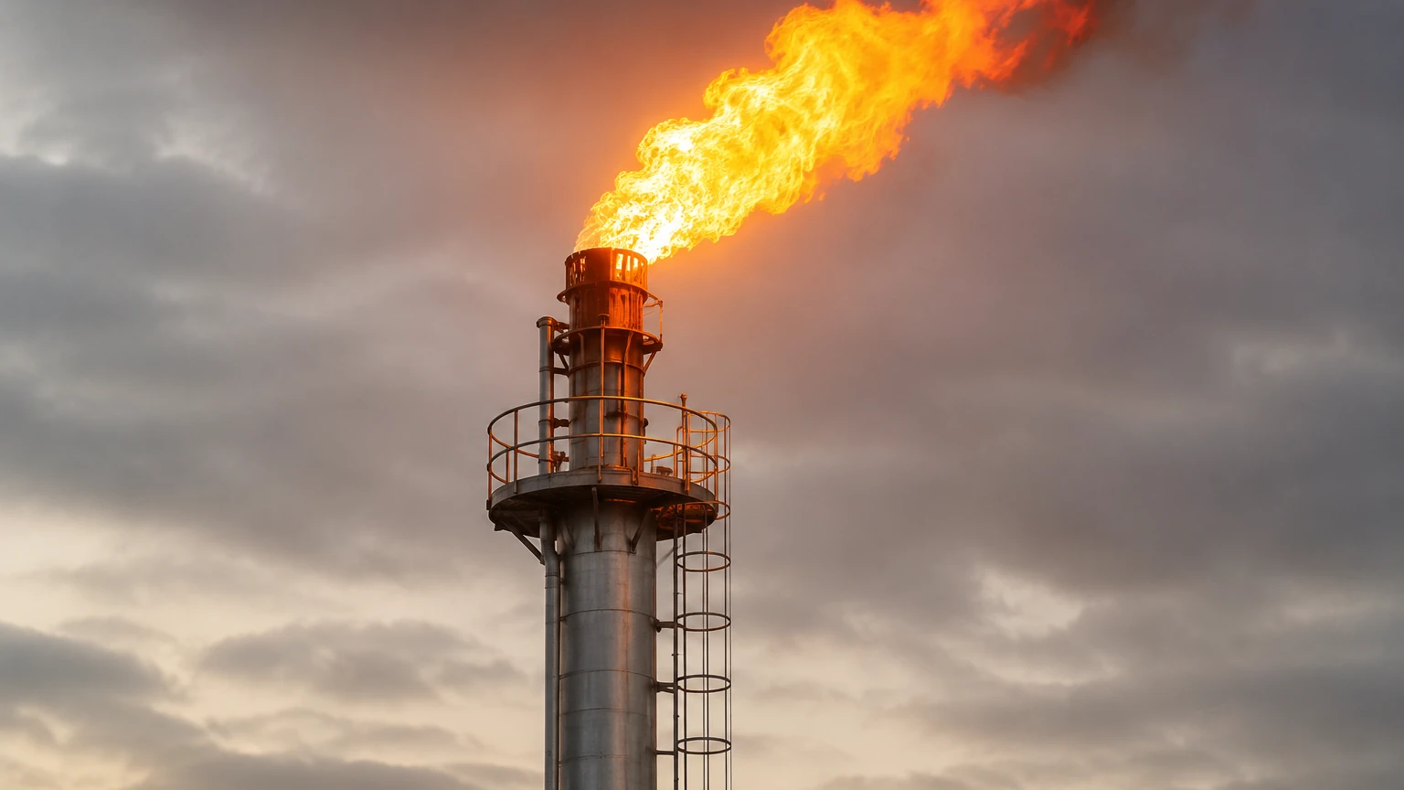
While the flare flow meter measures the gas, the overall safety of the flare system depends on the efficiency of the Flare Knockout Drum (KOD). The KOD's purpose is to separate liquid droplets from the gas stream before they reach the flare tip. Liquid carryover can cause "burning rain," which is a severe safety and environmental hazard.
Effective flare management requires high-reliability level measurement within the knockout drum. If the liquid level in the KOD rises too high, it must be detected immediately to trigger pump-out sequences or emergency shutdowns. Technologies such as guided wave radar or non-contact radar are often employed for this task due to their ability to handle varying liquid densities and potential foam. Integrating robust level sensors from manufacturers like Welk ensures that the flare flow meter is only measuring gas, thereby protecting the instrument from liquid damage and ensuring the accuracy of the flow data.
Common Risks and Technical Limitations
Despite advancements in technology, flare flow measurement faces several persistent risks:
* Acoustic Noise: High-pressure reducing valves upstream of the flare can generate ultrasonic noise that interferes with the meter's signal. Specialized noise-attenuating mounts or signal processing filters are often necessary.
* Liquid Slugs: While KODs remove most liquids, sudden surges can send "slugs" of liquid through the header. This can temporarily blind an ultrasonic meter or cause physical damage to insertion-style thermal probes.
* Contamination: Flare gas is often "dirty," containing soot, wax, or corrosive chemicals. Over time, these can build up on the sensors. Ultrasonic transducers are generally more resistant to this than thermal sensors, but periodic inspection is still required.
* Regulatory Scrutiny: In many jurisdictions, flare meters must be calibrated or verified annually. This can be difficult if the meter cannot be removed from service. In-situ verification techniques are becoming a standard requirement for modern flare meter designs.
Frequently Asked Questions (FAQ)
Q: Can a flare flow meter measure steam flow?
A: Many flare tips use steam for smokeless operation. While the main flare flow meter measures the waste gas, separate meters (often vortex or DP) are used for the steam line. However, some ultrasonic meters can be calibrated to measure steam, provided the temperature and pressure ratings are met.
Q: Why is mass flow more important than volumetric flow in flaring?
A: Environmental regulations typically require reporting in mass units (e.g., tonnes of CO2 equivalent). Since gas volume changes drastically with pressure and temperature, mass flow provides a consistent measurement of the actual amount of pollutants being processed.
Q: How does molecular weight affect the measurement?
A: In ultrasonic meters, the speed of sound is a function of the gas temperature and molecular weight. By measuring the speed of sound and temperature, the meter can calculate the molecular weight in real-time. This allows the system to distinguish between a heavy hydrocarbon leak and a light methane purge, which is essential for accurate mass flow calculation.
Q: What is the typical lifespan of a flare flow meter?
A: With proper maintenance and correct material selection (such as high-grade stainless steel or Hastelloy for corrosive gases), a high-quality ultrasonic flare meter can last 10 to 15 years. The transducers are the most common wear item and are often designed to be replaceable without breaking the process seal.
Conclusion
Implementing a flare flow meter is a complex engineering task that requires balancing regulatory requirements with the physical realities of the process. Ultrasonic transit-time technology remains the preferred choice for its wide turndown and ability to handle varying gas compositions. However, the success of the measurement system also relies on upstream process control, particularly the management of liquid levels in knockout drums. By selecting the correct measurement technologies and following rigorous installation standards, operators can ensure safety, maintain compliance, and gain better control over their facility's emissions profile.