Ultrasonic Level Control
Ultrasonic Level Control: A Comprehensive Engineering Guide
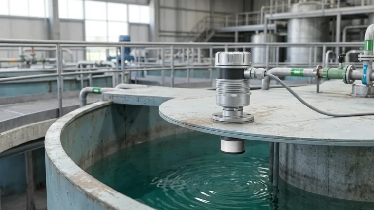
In modern industrial automation, maintaining precise fluid or solid levels is critical for process efficiency, safety, and inventory management. Ultrasonic level control has emerged as one of the most versatile and cost-effective non-contact measurement technologies. By utilizing high-frequency sound waves to determine the distance to a material surface, these systems provide reliable data without the wear and tear associated with mechanical probes. This guide explores the technical principles, system integration, and selection criteria for implementing effective level control solutions using ultrasonic technology.
Understanding the Principle of Ultrasonic Level Measurement
Before implementing an ultrasonic level control system, it is essential to understand the physics of the measurement. Ultrasonic sensors operate on the "Time-of-Flight" (ToF) principle. The device's transducer contains a piezoelectric crystal that converts electrical energy into mechanical vibrations, emitting a pulse of ultrasonic sound waves (typically in the range of 20 kHz to 80 kHz).
These waves travel through the air or gas space above the medium, reflect off the surface, and return to the transducer. The sensor then switches to "receiving mode" to detect the returning echo. The distance ($D$) between the sensor and the surface is calculated using the formula:
$$D = \frac{c \times t}{2}$$
Where:
* $c$ is the speed of sound in the medium (approximately 344 m/s in air at 20°C).
* $t$ is the total time elapsed between emission and reception.
Since the height of the vessel ($H$) is a known constant, the actual level ($L$) of the material is determined by subtracting the measured distance from the total height ($L = H – D$). Advanced Ultrasonic Level Meters incorporate microprocessors to filter out false echoes caused by internal tank structures, ensuring that only the signal from the actual material surface is processed.
Components of an Ultrasonic Level Control System
An integrated ultrasonic level control system consists of several key components that work together to automate process loops:
1. The Transducer/Sensor: The primary interface that generates and receives sound pulses. In compact designs, the electronics and transducer are housed in a single unit. In split-type systems, the sensor is mounted at the measurement point while the controller is located in a remote cabinet.
2. Signal Processing Unit: This unit converts the raw time-of-flight data into a standardized electrical signal. It also handles temperature compensation, as the speed of sound varies significantly with air temperature changes (approximately 0.17% per degree Celsius).
3. Output Interface: For control purposes, the meter typically provides a 4-20mA analog signal, representing 0% to 100% of the tank level. Digital communication protocols like RS485 (Modbus), HART, or Profibus are also common for integration into PLC and SCADA systems.
4. Control Elements: These include programmable relays within the meter that can trigger pumps, valves, or alarms directly when specific high or low setpoints are reached.
Key Selection Criteria for Ultrasonic Level Meters
Choosing the right instrument requires a detailed analysis of the application environment. The following table provides a comparison of typical specifications for industrial ultrasonic level control hardware:
Selection Table: Ultrasonic Level Meter Specifications
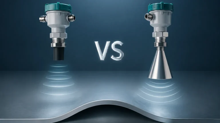
| Feature | Compact (Integrated) Meter | Split-Type Meter | High-Power Long-Range Meter |
| :— | :— | :— | :— |
| Measurement Range | 0.3m to 15m | 0.3m to 30m | Up to 40m |
| Output Options | 4-20mA, RS485 | 4-20mA, Relays, RS485 | 4-20mA, HART, Modbus |
| Power Supply | 24V DC / 220V AC | 24V DC / 220V AC | 24V DC / 220V AC |
| Beam Angle | 6° to 12° | 5° to 10° | 4° to 8° |
| Housing Material | ABS / PVC / PVDF | Aluminum / Stainless Steel | Reinforced Polymer / SS |
| Protection Class | IP65 / IP67 | IP68 (Sensor) / IP65 (Host) | IP68 |
Application Suitability
* Liquids: Ideal for water, wastewater, acids, and alkalis in open or closed tanks.
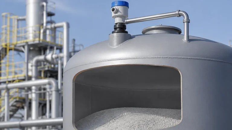
* Solids: Suitable for granules and pellets, though the range is often reduced by 50% compared to liquids due to the sound-absorbing nature of solids.
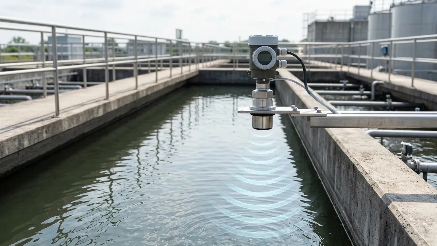
* Open Channels: Frequently used with flumes or weirs for flow rate monitoring in water treatment plants.
Installation Best Practices for Optimal Accuracy
Proper installation is the single most important factor in the success of ultrasonic level control. To ensure a clear signal path and accurate readings, engineers should follow these guidelines:
1. Positioning and Clearance
The sensor should be mounted perpendicular to the surface of the medium. It must be positioned away from the tank wall—ideally at a distance of at least 1/6th of the tank diameter—to prevent "wall echoes" from interfering with the measurement.
2. Avoiding the "Dead Zone"
Every ultrasonic sensor has a "dead zone" (also known as the blocking distance) directly beneath the transducer face, typically ranging from 0.2m to 0.6m depending on the frequency. If the material level enters this zone, the meter will provide erratic readings. The sensor should be mounted high enough so that the maximum expected level never enters this region.
3. Signal Obstructions
The ultrasonic beam spreads as it travels, forming a cone. Any internal obstructions such as ladders, heating coils, or agitator blades within this cone will reflect the signal. While modern software can "mask" these fixed echoes, it is best practice to install the sensor where the beam path is clear.
4. Turbulence and Inflow
Do not install the sensor directly above the tank's fill inlet. The falling stream of material will disrupt the ultrasonic pulse and cause signal loss. If the liquid surface is highly turbulent, a stilling well (a vertical pipe) can be used to provide a calm surface for measurement.
Managing Limitations and Environmental Factors
While highly effective, ultrasonic level control has physical limitations that must be addressed during the engineering phase:
* Vacuum Conditions: Sound waves require a medium (gas) to travel. Ultrasonic meters cannot function in a vacuum.
* High Pressure: Changes in pressure affect the density of the gas, which in turn alters the speed of sound. While most meters handle atmospheric pressure variations, high-pressure vessels may require specialized calibration or radar technology.
* Heavy Foam: Dense foam on a liquid surface acts as a sound absorber, significantly weakening or completely eliminating the return echo. In such cases, hydrostatic or radar sensors may be preferred.
* Dust and Vapor: Heavy dust in silos or thick steam in process tanks can scatter the ultrasonic signal. Using a sensor with a lower frequency and higher power can help penetrate these environments.
Practical Implementation of Ultrasonic Level Control
In a typical industrial setup, such as a chemical dosing tank, the ultrasonic level meter is used to maintain a constant supply. The meter's 4-20mA output is fed into a PID controller. As the level drops, the controller increases the speed of the feed pump. If the level reaches a critical low point, a relay in the meter triggers an emergency stop to prevent pump cavitation.
For remote monitoring, many facilities utilize RS485 Modbus communication. This allows a single twisted-pair cable to daisy-chain multiple Ultrasonic Level Meters back to a central workstation, reducing wiring costs and providing detailed diagnostic data, such as signal strength and temperature, alongside the level reading.
Frequently Asked Questions (FAQ)
Q: Can ultrasonic level meters be used for flammable liquids?
A: Yes, provided the instrument is rated for hazardous areas (Ex-proof or Intrinsically Safe). Always verify the ATEX or IECEx certification of the specific model before installation in such environments.
Q: How does wind affect measurement in outdoor tanks?
A: Strong wind can "blow" the ultrasonic pulse away from the receiver, especially over long distances. For outdoor applications with ranges exceeding 10 meters, it is recommended to use a sensor with a higher power output or a protective sun/wind shield.
Q: Does the color or transparency of the liquid affect the reading?
A: No. Unlike optical sensors, ultrasonic technology is completely unaffected by the color, transparency, or dielectric constant of the material. It only requires a physical surface that can reflect sound.
Q: What maintenance is required for these systems?
A: Because they are non-contact, maintenance is minimal. However, the transducer face should be checked periodically for condensation or material buildup, which can be wiped away with a soft cloth.
Conclusion
Ultrasonic level control offers a robust, non-invasive solution for a wide array of industrial challenges. By understanding the interaction between sound waves and the process environment, engineers can design systems that provide high accuracy and long-term reliability. Whether managing water resources or controlling chemical inventories, the correct application of Ultrasonic Level Meters remains a cornerstone of modern process instrumentation. When selecting a device, always prioritize models with integrated temperature compensation and advanced echo-filtering capabilities to ensure performance in fluctuating industrial conditions.