Ultrasonic Level Sensor Sick
Ultrasonic Level Sensor Sick: A Technical Guide to Selection and Industrial Application
In the landscape of industrial automation and process control, non-contact level measurement has become a standard for reliability and hygiene. Among the various technologies available, ultrasonic sensors are frequently selected for their versatility and cost-effectiveness. Engineers often look toward established brands, such as the ultrasonic level sensor sick range, as a benchmark for performance. However, selecting the right instrument requires a deep understanding of acoustic principles, environmental constraints, and the specific requirements of the application.
This guide explores the technical foundations of Ultrasonic Level Meters, evaluates the criteria used when comparing market-leading sensors like those from Sick with broader industrial solutions, and provides practical installation and maintenance advice for process engineers.
Understanding Ultrasonic Measurement Principles
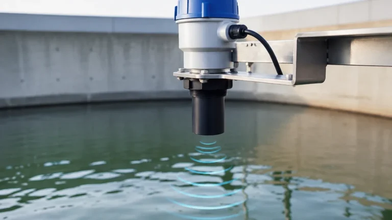
Ultrasonic level measurement operates on the "Time-of-Flight" (ToF) principle. The instrument’s transducer contains a piezoelectric crystal that, when energized, vibrates at a specific frequency to emit a burst of ultrasonic sound waves. These waves travel through the air or gas medium until they strike the surface of the target material (liquid or solid).
Upon impact, a portion of the sound energy is reflected back toward the sensor. The transducer then acts as a receiver, converting the returning mechanical energy back into an electrical signal. The internal electronics measure the time interval between the emission of the pulse and the reception of the echo.
The Distance Calculation
The distance ($D$) from the sensor to the material surface is calculated using the formula:
$$D = \frac{c \times t}{2}$$
Where:
* $c$ is the speed of sound in the medium (approximately 343 m/s in air at 20°C).
* $t$ is the total time elapsed for the round trip.
The level of the material in the tank is then determined by subtracting the measured distance from the total height of the vessel ($H$):
$$Level = H – D$$
Factors Affecting the Speed of Sound
One of the most critical aspects of ultrasonic measurement is that the speed of sound is not constant. It is heavily influenced by the temperature of the medium. For every 1°C change in temperature, the speed of sound changes by approximately 0.17%. To maintain accuracy, high-quality ultrasonic level meters incorporate integrated temperature sensors to provide real-time compensation for these fluctuations.
Evaluating the Ultrasonic Level Sensor Sick and Industrial Alternatives
When procurement teams search for an "ultrasonic level sensor sick," they are typically looking for the reliability associated with the Sick UM30 or UC series. These sensors are known for their compact form factors and integration capabilities, such as IO-Link. However, for large-scale industrial process applications—such as deep wastewater sumps or corrosive chemical storage—it is essential to compare these against specialized industrial level meters designed for harsher environments.
Key Evaluation Criteria
When evaluating a sensor for a B2B application, consider the following technical parameters:
1. Sensing Range: Standard industrial sensors typically cover ranges from 0.1 m up to 30 m. While compact sensors like the Sick UM series excel in short-range factory automation (up to 8 m), heavy-duty industrial meters are required for tall silos or large reservoirs.
2. Beam Angle: A narrower beam angle (typically 5° to 12°) is preferable as it allows the sensor to be used in narrow tanks or near internal obstructions like ladders and agitators without generating false echoes.
3. Output Protocols: Modern systems require more than just a 4-20mA analog signal. Look for compatibility with HART, Modbus RTU, or IO-Link to facilitate remote diagnostics and parameterization.
4. Housing Material: For chemical applications, PVDF or PTFE-coated transducers are necessary to prevent corrosion, whereas stainless steel or PBT plastics may suffice for general water treatment.
Industrial Selection Table
The following table provides a comparison of typical specifications found in professional-grade ultrasonic level meters used in process industries.
| Feature | Compact Automation Sensor (e.g., Sick UC/UM) | Industrial Process Meter (e.g., Welk Series) |
| :— | :— | :— |
| Max Range | 0.25 m – 8.0 m | 5.0 m – 30.0 m |
| Accuracy | ±1% of final value | ±0.25% to ±0.5% of range |
| Beam Angle | Wide (approx. 10°-15°) | Narrow (approx. 5°-8°) |
| Display | LED/Numeric on device | Backlit LCD with Echo Curve display |
| Output | Analog / IO-Link | 4-20mA / HART / RS485 Modbus |
| Operating Temp | -25°C to +70°C | -40°C to +80°C (Extended options) |
| Protection Class | IP65 / IP67 | IP66 / IP68 (Submersible options) |
Installation Best Practices and the "Dead Zone"
Successful implementation of an ultrasonic level meter depends heavily on correct physical installation. Even the highest quality sensor will fail if the acoustic path is compromised.
The Dead Zone (Blocking Distance)
Every ultrasonic sensor has a "dead zone" or "blocking distance" directly in front of the transducer face. In this region, the sensor cannot accurately measure because the transducer is still vibrating from the initial pulse emission and cannot yet switch to receiving mode.
* Typical Dead Zone: Ranges from 100 mm to 800 mm depending on the frequency of the sensor.
* Mitigation: The sensor must be mounted high enough so that the maximum expected liquid level never enters the dead zone. If the tank is filled into the dead zone, the sensor may report a "full" error or provide an erratic, incorrect reading.
Mounting Considerations
* Perpendicularity: The sensor face must be perfectly parallel to the liquid surface. A tilt of even a few degrees can cause the signal to bounce away from the receiver rather than back to it, resulting in signal loss.
* Wall Proximity: Do not mount the sensor too close to the tank wall. The sound wave spreads as it travels (the "cone"). If the cone hits the wall, it creates parasitic echoes. A general rule is to keep the sensor at a distance from the wall equal to at least 1/6th of the tank height.
* Inlet Interference: Never mount the sensor directly above the tank inlet. The falling liquid or solids will interrupt the ultrasonic pulse and cause false readings.

Environmental Limitations and Mitigation
While ultrasonic level meters are robust, certain environmental factors can degrade their performance. Understanding these limitations is key to deciding whether to use ultrasonic technology or switch to radar.
1. Foam and Turbulence
Heavy foam on the surface of a liquid acts as an acoustic absorber. Instead of reflecting the sound wave, the foam dissipates the energy, leading to a "Loss of Echo" (LOE) condition. If foam is present, a high-power industrial sensor with advanced signal processing or a radar level meter may be required.
2. Dust and Vapor
Heavy dust (in silos) or dense steam/vapor (in hot tanks) can attenuate the ultrasonic signal. While ultrasonic sensors can handle moderate dust, extreme conditions may require a sensor with a lower frequency (which penetrates dust better) or a non-contact radar sensor which is unaffected by air density changes.
3. Vacuum and Pressure
Sound requires a medium to travel. Therefore, ultrasonic sensors cannot function in a vacuum. Furthermore, high pressure changes the density of the air, which significantly alters the speed of sound and can cause measurement errors if not properly compensated for. Most ultrasonic meters are limited to a pressure range of 0.7 bar to 3 bar absolute.
Application-Specific Considerations
Water and Wastewater Treatment
In sumps, wet wells, and open channels, ultrasonic sensors are the industry standard. They are preferred here because they are unaffected by the dielectric constant of the water and are resistant to the fouling that plagues submerged hydrostatic pressure sensors. For these applications, ensure the sensor has an IP68 rating to survive occasional flooding.
Chemical Storage
When measuring acids or bases, the chemical compatibility of the transducer face is paramount. Standard sensors often use an epoxy or aluminum face which can be corroded. Selecting a sensor with a PVDF (Polyvinylidene fluoride) housing ensures longevity in corrosive environments.
Maintenance and Troubleshooting FAQ
Q: Why is my sensor reading "Full" when the tank is empty?
A: This is often caused by a "ringing" echo or a reflection from a nearby obstruction (like a bracket) that the sensor interprets as the surface. Check the mounting position and ensure there are no objects within the beam cone. Many industrial meters allow for "False Echo Suppression," where you can tell the software to ignore specific echoes at fixed distances.
Q: How often should I clean the transducer face?
A: In most clean liquid applications, the transducer is self-cleaning due to its vibration. However, in high-humidity or dusty environments, condensation or crusting can occur. A soft cloth and water or a mild detergent are usually sufficient. Avoid using sharp tools or abrasive cleaners that could damage the piezoelectric surface.
Q: Can I use an ultrasonic sensor for solids like grain or sand?
A: Yes, but with caveats. Solids do not have a flat surface; they have an "angle of repose." This means the signal will be scattered. You must select a sensor specifically rated for solids, which typically features higher power and specialized algorithms to process the diffuse reflections.
Q: How does the Sick IO-Link functionality compare to standard 4-20mA?
A: IO-Link provides digital data transmission, allowing for the transfer of not just the level measurement, but also the internal temperature, signal quality, and device status. It simplifies wiring and allows for automatic parameter backup, which is useful for rapid sensor replacement in automated factory lines.
For engineers and procurement specialists, choosing between an ultrasonic level sensor sick and a specialized industrial meter involves balancing the need for compact integration with the demands of the process environment. By adhering to strict installation guidelines and understanding the physical limits of acoustic measurement, users can ensure high accuracy and long-term reliability in their level control systems.
For more detailed technical specifications and to explore a range of solutions tailored to specific industrial needs, you may Review product options and application support to find the ideal match for your facility's requirements.