Ultrasonic Level Sensor Troubleshooting
Ultrasonic Level Sensor Troubleshooting: A Practical Engineering Guide
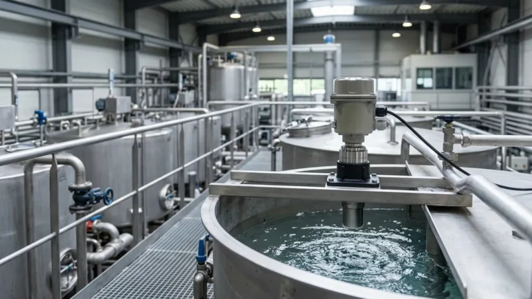
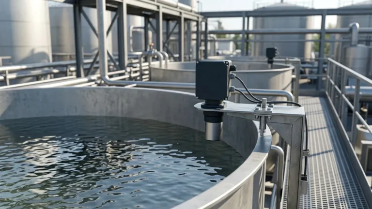
In the landscape of industrial process control, Ultrasonic Level Meters have become a standard solution for non-contact level measurement. Their popularity stems from their lack of moving parts and their ability to measure liquid and solid levels without making physical contact with the medium. However, like any sophisticated instrumentation, they are subject to environmental and installation-related challenges.
Effective ultrasonic level sensor troubleshooting requires a foundational understanding of how these devices interact with their environment. When a sensor fails or provides erratic data, the cause is rarely a hardware malfunction; instead, it is often a mismatch between the sensor's physical principles and the specific conditions of the application.
The Principle of Ultrasonic Level Measurement
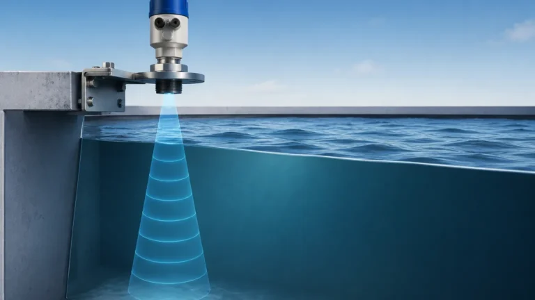
Before addressing specific troubleshooting steps, it is essential to understand the physics of the measurement. Ultrasonic sensors operate on the "Time-of-Flight" (ToF) principle.
The sensor's transducer contains a piezoelectric crystal that, when energized, vibrates at a specific frequency (typically between 20 kHz and 200 kHz). This vibration generates a mechanical sound wave that travels through the air toward the target medium. When the wave hits the surface, it is reflected back to the transducer, which now acts as a receiver.
The distance is calculated using the formula:
Distance = (Speed of Sound × Time) / 2
Because the speed of sound in air is approximately 343 meters per second at 20°C, the device can calculate the level by subtracting the measured distance from the total tank height. However, the speed of sound is highly dependent on temperature and the composition of the gas through which it travels—factors that are central to many troubleshooting scenarios.
Selection Criteria for Ultrasonic Instrumentation
Choosing the correct hardware is the first step in preventing operational issues. The following table outlines the primary evaluation criteria for selecting ultrasonic level meters in industrial environments.
| Feature | Specification Range | Engineering Consideration |
| :— | :— | :— |
| Measurement Range | 0.25m to 30m | Ensure the maximum range exceeds the tank height by at least 20%. |
| Beam Angle | 5° to 12° | Narrower beam angles are preferred for tall, narrow tanks to avoid wall interference. |
| Frequency | 20 kHz to 80 kHz | Higher frequencies offer better resolution; lower frequencies penetrate dust/vapor better. |
| Operating Temperature | -40°C to +80°C | Accuracy degrades significantly if the sensor lacks temperature compensation. |
| Output Signal | 4-20mA, RS485, HART | Compatibility with existing PLC/SCADA systems is vital for data integrity. |
| Blanking Distance | 0.2m to 0.8m | The "Dead Zone" where measurement is impossible; must be accounted for in tank design. |
Core Ultrasonic Level Sensor Troubleshooting Steps
When a sensor provides an error code or an incorrect reading, engineers should follow a systematic diagnostic path. Most issues fall into three categories: signal loss, false echoes, and accuracy drift.
1. Diagnosing Loss of Echo (Signal Failure)
If the sensor displays a "Loss of Echo" error (often E04 or E01 depending on the manufacturer), the transducer is not receiving a return signal strong enough to process.
* Surface Turbulence: Heavy agitation or splashing can scatter the sound waves, preventing them from returning to the sensor.
* *Solution:* Increase the damping/averaging time in the sensor settings or install a stilling well to provide a calm surface for measurement.
* Foam Absorption: Certain types of foam act as an acoustic insulator, absorbing the sound wave rather than reflecting it.
* *Solution:* If the foam is thick and dense, ultrasonic technology may not be suitable. Consider switching to a radar level meter or a hydrostatic transmitter.
* Transducer Contamination: Condensation, dust buildup, or chemical scaling on the transducer face can dampen the vibration.
* *Solution:* Clean the transducer face with a soft cloth and mild solvent. If condensation is a recurring issue, ensure the sensor is mounted at a slight angle or use a sensor with a self-cleaning (vibrating) face.
2. Identifying False Echoes and Ghost Readings
False echoes occur when the sound wave reflects off an object other than the liquid surface, such as a ladder, a pipe, or the tank wall.
* The "Full Tank" Error: If the sensor reports a full tank when it is actually empty, it may be locked onto a reflection from an internal obstruction or the "ringing" of the transducer itself.
* *Solution:* Perform a "False Echo Mapping" or "Fixed Echo Suppression." Most modern Ultrasonic Level Meters allow the user to record the echoes of an empty tank and tell the software to ignore them.
* Wall Interference: If the sensor is mounted too close to the tank wall, the beam (which spreads as it travels) will hit the wall and return a premature signal.
* *Solution:* Ensure the sensor is mounted at least 200mm to 500mm away from the wall, depending on the beam angle and depth of the tank.
3. Resolving Accuracy and Drift Issues
If the sensor provides a reading that is consistently off by a few centimeters or fluctuates wildly, the issue is likely environmental.
* Temperature Gradients: Since the speed of sound changes by 0.17% per degree Celsius, a sensor measuring a tank in direct sunlight may provide inaccurate data if the internal temperature sensor is not calibrated to the air space temperature.
* *Solution:* Use a remote temperature sensor if the transducer is exposed to solar heating while the tank air space remains cool.
* Vapor and Gas Composition: Ultrasonic waves are calibrated for the speed of sound in air. If the tank contains heavy vapors (like CO2 or refrigerants), the speed of sound changes, leading to massive errors.
* *Solution:* Recalibrate the sensor for the specific gas constant of the vapor or switch to radar technology, which is unaffected by gas composition.
Installation Best Practices to Minimize Troubleshooting
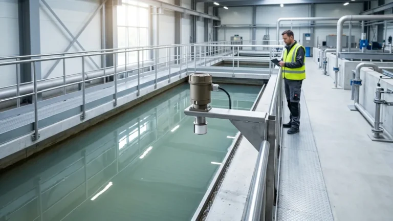
Proper installation is the most effective way to reduce future ultrasonic level sensor troubleshooting efforts. Adhere to the following engineering guidelines:
1. Avoid the Center: Do not mount the sensor in the exact center of a circular tank. This can create a parabolic effect where multiple echoes converge, confusing the sensor.
2. Avoid Fill Streams: Never install the sensor directly above the inlet pipe. The falling liquid will obstruct the ultrasonic beam and cause erratic readings.
3. Perpendicularity: The transducer face must be perfectly horizontal (perpendicular to the liquid surface). Even a 2-degree tilt can significantly reduce the strength of the return signal in tall tanks.
4. The Dead Zone (Blanking Distance): Ensure the maximum liquid level never enters the sensor's blanking distance (typically the top 20cm to 60cm). If the liquid enters this zone, the sensor will provide a "lock-on" error or jump to a random reading.

Technical Limitations of Ultrasonic Technology
While versatile, ultrasonic sensors have hard physical limits. Troubleshooting will be unsuccessful if the application exceeds these boundaries:
* Vacuum Applications: Sound cannot travel through a vacuum. If the process involves a vacuum, ultrasonic sensors will not work.
* High Pressure: In pressures exceeding 3 bar (approx. 43 PSI), the density of the air changes the acoustic impedance, often making it difficult for the transducer to launch a wave effectively.
* Extreme Temperatures: Most ultrasonic transducers are limited to 80°C. Beyond this, the piezoelectric elements and the housing materials may degrade.
Frequently Asked Questions (FAQ)
Q: Why does my sensor work fine at night but fail during the day?
A: This is usually due to temperature-induced changes in the speed of sound or solar heating of the transducer. Direct sunlight can heat the sensor housing to temperatures much higher than the ambient air, causing the internal temperature compensation to overcorrect. Installing a sunshade often resolves this.
Q: Can I use an ultrasonic sensor to measure the level of solids like grain or sand?
A: Yes, but with caveats. Solids do not reflect sound as efficiently as liquids and often have an "angle of repose" that reflects the signal away from the sensor. You should use a sensor with a higher power output and a lower frequency (e.g., 20-30 kHz) for solids.
Q: My sensor is showing a stable reading, but the tank is empty. What is happening?
A: This is a classic "fixed echo" issue. The sensor has likely locked onto a reflection from a weld seam, a ladder rung, or a build-up of material on the tank wall. You need to perform a false echo mapping to mask out that specific distance.
Q: How often should I calibrate my ultrasonic level meter?
A: In stable environments, an annual check is sufficient. However, if the medium changes or if the tank is subject to extreme seasonal temperature shifts, semi-annual verification against a manual tape measure is recommended.
Conclusion
Successful ultrasonic level sensor troubleshooting is a blend of understanding acoustic physics and applying practical site observations. By ensuring the sensor is correctly matched to the medium, mounted according to geometric best practices, and programmed to ignore environmental obstructions, engineers can achieve highly reliable level data. For complex applications involving heavy foam or high-pressure vapors, consulting with a specialist manufacturer like Welk can help determine if ultrasonic technology remains the optimal choice or if alternative methods should be explored.
For more detailed technical specifications and product selection support, Review product options and application support to ensure your instrumentation matches your process requirements.