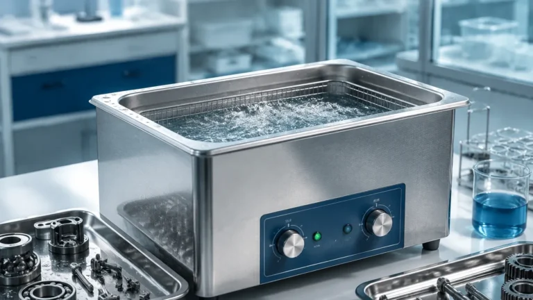
Ultrasonic Water Level Indicator Using Arduino
Ultrasonic Water Level Indicator Using Arduino: From Prototyping to Industrial Application
Level measurement is a fundamental requirement across various sectors, including water treatment, chemical processing, and agricultural management. Among the diverse technologies available, ultrasonic sensing has emerged as a preferred non-contact method due to its reliability and ease of integration. For engineers and hobbyists alike, developing an ultrasonic water level indicator using arduino serves as an excellent entry point for understanding the complexities of fluid dynamics and electronic sensing.
However, while a microcontroller-based prototype is ideal for proof-of-concept or small-scale residential use, industrial environments demand a higher level of precision and durability. This guide explores the principles of ultrasonic measurement, the steps to build a basic indicator, and the critical transition points where professional Ultrasonic Level Meters become necessary for operational safety and accuracy.
Understanding the Measurement Principle: Time-of-Flight (ToF)
Ultrasonic level measurement relies on the propagation of high-frequency sound waves—typically above the range of human hearing (20 kHz to 200 kHz). The sensor functions by emitting an ultrasonic pulse from a transducer. This pulse travels through the air, reflects off the surface of the liquid, and returns to the sensor.
The Mathematical Foundation
The distance between the sensor and the water surface is calculated using the Time-of-Flight (ToF) principle. The formula is expressed as:
Distance = (Speed of Sound × Time) / 2
The factor of two is used because the sound wave travels to the surface and back. In standard atmospheric conditions at 20°C (68°F), the speed of sound is approximately 343 meters per second (1,125 ft/s).
Environmental Variables
It is important to note that the speed of sound is not constant; it fluctuates based on the temperature of the medium (air). For high-accuracy applications, temperature compensation is required. The speed of sound ($v$) can be more accurately estimated using:
$v ≈ 331.5 + 0.6 imes T$
Where $T$ is the temperature in degrees Celsius. Professional-grade sensors usually include an integrated temperature sensor to automate this calculation, ensuring consistent readings across varying climates.
Building an Ultrasonic Water Level Indicator Using Arduino
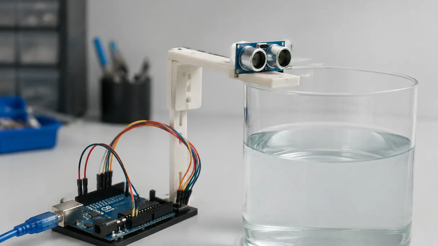
Creating a basic monitoring system requires a few core components. For a prototype, the Arduino Uno or Nano is the most common choice due to its extensive library support.
Required Components
1. Microcontroller: Arduino Uno or compatible board.
2. Ultrasonic Sensor:
* HC-SR04: Common for indoor, dry environments.
* JSN-SR04T: A waterproof version better suited for water tanks and outdoor use.
3. Output Device: I2C LCD (16×2) or an OLED display to show the level in centimeters (cm) or inches (in).
4. Power Supply: 5V to 9V DC source.
5. Accessories: Jumper wires, breadboard, and a waterproof enclosure for the electronics.
Wiring and Logic
The ultrasonic sensor typically has four pins: VCC (5V), GND, Trig (Trigger), and Echo. The Trigger pin receives a short pulse from the Arduino to start the measurement, while the Echo pin sends a pulse back to the Arduino, the duration of which represents the time taken for the sound to return.
In the Arduino IDE, the `PulseIn` function is used to measure the duration of the Echo pulse. This value is then converted into distance. To determine the "Water Level" rather than just the "Distance to Water," you must subtract the measured distance from the total height of the tank.
Water Level = Total Tank Height – Measured Distance
Technical Limitations of DIY Microcontroller Systems
While an ultrasonic water level indicator using arduino is effective for monitoring a home rain barrel or a small laboratory tank, it faces significant hurdles in industrial or municipal settings:
* Signal Processing: DIY systems often struggle with "noise" caused by internal tank structures (ladders, pipes) or surface turbulence. Industrial meters use advanced Echo Processing algorithms to filter out false reflections.
* Environmental Protection: Standard Arduino components are sensitive to humidity, corrosive vapors, and extreme temperatures. Industrial units are typically rated IP65 to IP68.
* Output Standards: Arduino outputs are usually TTL (5V) or Serial. Industrial control systems (PLCs/SCADA) require standard 4-20mA analog signals, Modbus RTU, or HART protocols for long-distance transmission without signal loss.
* Power Stability: Industrial sites often have fluctuating power or require 24V DC loop-powered configurations, which are more complex to implement with basic microcontrollers.
Transitioning to Industrial Ultrasonic Level Meters
When a project moves from a prototype to a critical infrastructure application—such as wastewater treatment plants, chemical storage, or large-scale irrigation—upgrading to professional hardware is essential. Modern Ultrasonic Level Meters integrate the sensor, transmitter, and signal processor into a single, robust housing.
Comparison Table: DIY vs. Industrial Solutions
| Feature | Arduino-based Prototype | Industrial Ultrasonic Meter |
| :— | :— | :— |
| Accuracy | ±1% to 3% (variable) | ±0.2% to 0.5% of range |
| Measurement Range | 2cm to 4m (6.5ft to 13ft) | 0.3m to 30m+ (1ft to 100ft+) |
| Housing | Custom/3D Printed | PVDF, PP, or Stainless Steel |
| Signal Output | LCD / Serial / WiFi | 4-20mA, HART, Modbus, Relays |
| Temperature Comp. | Manual/External Sensor | Integrated Automatic Compensation |
| Ease of Install | High (Coding required) | Plug-and-Play (Menu-driven setup) |
Critical Installation Considerations
Whether you are installing a DIY sensor or a professional instrument, certain physical laws govern the success of ultrasonic measurement.
1. The Dead Zone (Blocking Distance)
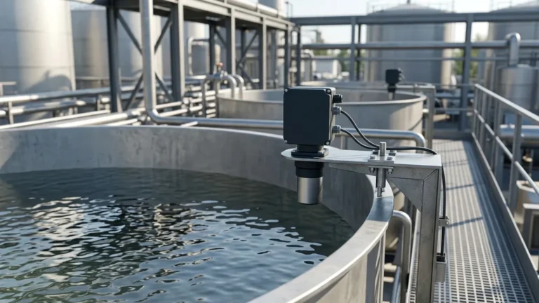
Every ultrasonic sensor has a "Dead Zone" directly in front of the transducer face. In this zone, the sensor cannot accurately process the returning pulse because it is still vibrating from the transmission. For small sensors, this might be 10cm to 20cm (4 to 8 inches); for large industrial sensors, it can be up to 50cm (20 inches). Ensure the sensor is mounted high enough that the water level never enters this zone.
2. Beam Angle and Obstructions
The ultrasonic pulse spreads out in a cone shape, typically between 5° and 15°. If this beam hits a tank wall, a ladder, or a cooling coil, it will return a false "High Level" reading.
* Rule of Thumb: Install the sensor at least 200mm (8 inches) away from the tank wall for every 1 meter (3.3 feet) of depth.
3. Surface Conditions
Ultrasonic waves require a solid or liquid surface to reflect off.
* Foam: Heavy foam absorbs the ultrasonic pulse, leading to a "Loss of Echo" error.
* Turbulence: Rapidly moving or boiling water can scatter the signal. In these cases, a stilling well (a vertical pipe) can be used to provide a calm surface for measurement.
* Vapor/Steam: High concentrations of steam can change the speed of sound significantly, requiring specialized high-frequency transducers or radar-based alternatives.
Troubleshooting Common Issues
If your ultrasonic water level indicator using arduino or industrial meter provides erratic readings, check the following:
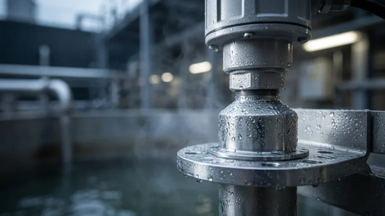
* Condensation: Water droplets on the transducer face will block the signal. Industrial sensors often have a self-cleaning effect due to the vibration of the transducer, but DIY sensors may need a protective, thin plastic film or regular cleaning.
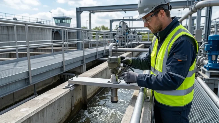
* Alignment: Ensure the sensor is perfectly perpendicular to the water surface. Even a 5° tilt can cause the signal to bounce away from the receiver rather than back to it.
* Power Noise: In industrial settings, VFDs (Variable Frequency Drives) can create electrical noise. Ensure shielded cables are used and properly grounded.
Frequently Asked Questions (FAQ)
Q: Can ultrasonic sensors measure the level of solids like grain or sand?
A: Yes, but with limitations. Solids do not reflect sound as efficiently as liquids and often have an "angle of repose" that scatters the signal. Higher-powered industrial sensors with specialized software are required for solids.
Q: Is there a maximum depth for ultrasonic measurement?
A: Most standard industrial ultrasonic meters are effective up to 15-20 meters (50-65 feet). Beyond this, the signal attenuation in the air becomes too great, and Radar (GWR or Non-contact) is usually recommended.
Q: How does pressure affect the ultrasonic level meter?
A: Ultrasonic sensors are generally designed for atmospheric pressure. High pressure increases the density of the air, which changes the speed of sound and can damage the transducer face. For pressurized tanks, radar or hydrostatic transmitters are better choices.
Q: Can I use an Arduino for 24/7 industrial monitoring?
A: While possible, it is not recommended for critical applications. The lack of industrial-grade surge protection, thermal management, and standardized mounting makes it a liability in professional environments. It is best used for prototyping the logic before deploying a certified Ultrasonic Level Meter.
Conclusion
Developing an ultrasonic water level indicator using arduino is a valuable exercise for understanding the physics of non-contact sensing and the basics of data acquisition. It provides a cost-effective way to monitor non-critical systems and learn the nuances of ToF measurement.
However, for process industries where accuracy, longevity, and integration are paramount, professional ultrasonic solutions provide the necessary reliability. By understanding the limitations of the technology—such as dead zones, beam angles, and environmental interference—engineers can select the right tool for the job, ensuring efficient and safe liquid management across any application.
Download Ultrasonic Water Level Indicator Using Arduino as a PDF