Ultrasonic Sensor Minimum Range
Ultrasonic Sensor Minimum Range: A Comprehensive Engineering Guide
In the field of industrial automation and process control, ultrasonic technology remains one of the most versatile and cost-effective methods for non-contact level measurement. However, for engineers and plant managers, the successful implementation of Ultrasonic Level Meters depends heavily on understanding a critical technical constraint: the ultrasonic sensor minimum range, often referred to as the "dead zone" or "blocking distance."
Selecting a sensor without accounting for this physical limitation can lead to inaccurate readings, system failures, or even tank overflows. This guide provides a detailed technical overview of why this minimum range exists, how to calculate it, and practical strategies for managing it in industrial environments.
The Principle of Ultrasonic Level Measurement
To understand the ultrasonic sensor minimum range, one must first understand the fundamental physics of the measurement process. Ultrasonic sensors operate on the Time-of-Flight (ToF) principle.
Time-of-Flight (ToF) Dynamics
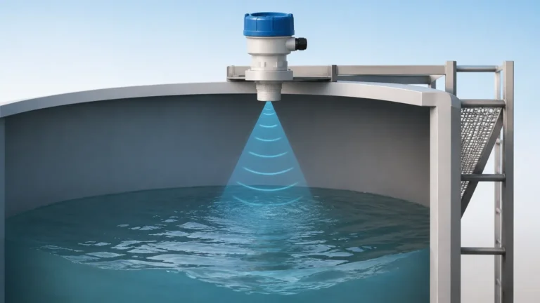
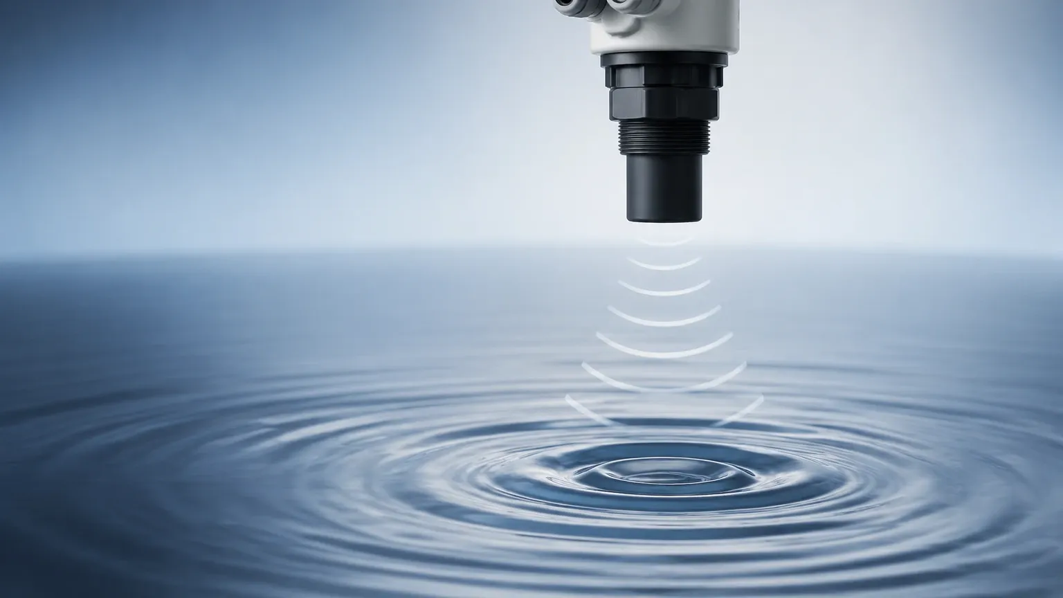
The sensor’s transducer contains a piezoelectric crystal that converts electrical energy into mechanical vibrations, creating high-frequency sound waves. These waves travel through the air, reflect off the surface of the material (liquid or solid), and return to the transducer. The sensor then converts the reflected sound back into an electrical signal.
The distance ($D$) is calculated using the formula:
$$D = \frac{c \times t}{2}$$
Where:
* $c$ is the speed of sound in the medium (approximately 343 m/s in air at 20°C).
* $t$ is the total time elapsed between the emission of the pulse and the reception of the echo.
The "Ringing" Effect and the Dead Zone
The ultrasonic sensor minimum range is a direct result of the transducer's mechanical design. When the piezoelectric crystal is excited, it does not stop vibrating instantaneously after the pulse is emitted. It continues to vibrate for a few milliseconds, a phenomenon known as "ringing."
During this ringing period, the transducer is physically incapable of accurately detecting a returning echo because its own vibration masks the incoming signal. Consequently, any object or material surface located too close to the transducer—within the distance the sound travels during this ringing phase—cannot be measured. This area is the "dead zone."
Factors Influencing Ultrasonic Sensor Minimum Range
The specific minimum range of a sensor is not a universal constant; it varies based on several engineering factors:
1. Operating Frequency
Frequency is the primary determinant of both the maximum range and the dead zone.
* High-Frequency Sensors (e.g., 60 kHz – 100 kHz): These sensors have smaller transducers with less mass, which stop vibrating more quickly. This results in a shorter ultrasonic sensor minimum range (typically 0.1 m to 0.25 m). However, high-frequency waves dissipate faster, limiting the total effective range.
* Low-Frequency Sensors (e.g., 10 kHz – 30 kHz): These require larger transducers to move more air for long-distance measurement. These larger components have more inertia and ring for a longer duration, resulting in a larger dead zone (often 0.5 m to 1.0 m or more).
2. Transducer Material and Damping
Manufacturers like Welk use specialized damping materials and electronic filtering to reduce the ringing time. A well-engineered sensor can achieve a tighter minimum range by utilizing advanced signal processing to distinguish between residual ringing and a true echo.
3. Environmental Temperature
The speed of sound is temperature-dependent. As temperature increases, sound travels faster. While this primarily affects the accuracy of the distance calculation, it also slightly shifts the physical boundaries of the dead zone in terms of time-to-distance conversion.
Practical Selection Table for Ultrasonic Level Meters
When specifying Ultrasonic Level Meters, engineers must balance the required measurement depth with the available headspace in the tank. The following table illustrates typical relationships between frequency, maximum range, and the ultrasonic sensor minimum range.
| Sensor Frequency | Typical Max Range (Liquids) | Typical Minimum Range (Dead Zone) | Common Applications |
| :— | :— | :— | :— |
| 80 kHz | 5 meters (16.4 ft) | 0.20 m (0.65 ft) | Small chemical tanks, IBC totes, sumps |
| 60 kHz | 10 meters (32.8 ft) | 0.25 m – 0.30 m | Standard water storage, buffer tanks |
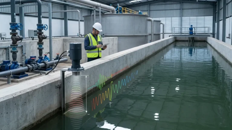
| 40 kHz | 15 meters (49.2 ft) | 0.50 m – 0.60 m | Large wastewater basins, open channels |
| 20 kHz | 30+ meters (98.4 ft) | 0.80 m – 1.20 m | Tall silos, large reservoirs, grain storage |
*Note: These values are representative. Specific performance depends on the manufacturer's transducer design and signal processing capabilities.*
Installation Considerations and Strategies
Because the ultrasonic sensor minimum range represents a "blind spot," installation geometry is critical. If the liquid level rises into the dead zone, the sensor may output an error code, a "lost echo" signal, or—more dangerously—a fixed value that suggests the tank is not yet full.
Offset Mounting
The most common way to manage a large dead zone is to mount the sensor higher than the maximum possible liquid level.
* Nozzles and Standpipes: If the tank is frequently filled to the top, the sensor can be mounted on a nozzle or a standpipe. This effectively moves the transducer face away from the liquid, placing the dead zone inside the pipe rather than inside the tank volume.
* Consideration: When using standpipes, the pipe must be smooth and have a diameter large enough to prevent the ultrasonic beam from hitting the pipe walls, which would cause false echoes. Typically, a 2-inch to 4-inch (50mm to 100mm) pipe is used depending on the beam angle.
Beam Angle and Obstructions
Ultrasonic waves spread in a cone shape (typically 5° to 12°). When calculating the mounting position to account for the minimum range, ensure that the beam does not intersect with ladders, pipes, or agitators. Reflections from these obstructions can interfere with the sensor's ability to process the primary echo, especially near the boundaries of the dead zone.
Atmospheric Conditions
In pressurized tanks or environments with heavy vapor (such as steam or chemical fumes), the speed of sound changes. While this does not change the "ringing" time of the transducer, it affects how the sensor interprets the distance. Always use sensors with integrated temperature compensation to maintain accuracy across the entire measurement range.
Limitations and Risks of Ignoring Minimum Range
Failure to account for the ultrasonic sensor minimum range can lead to several operational risks:
1. Tank Overfills: If the level enters the dead zone and the sensor fails to report an increase, automated filling systems may not shut off, leading to environmental hazards and product loss.
2. "Lock-up" Errors: Some sensors may "lock" on the last valid reading before the level entered the dead zone. This provides a false sense of security to operators.
3. Signal Instability: Near the edge of the minimum range, the signal may fluctuate wildly as the sensor struggles to distinguish the echo from the transducer's residual vibration.
Frequently Asked Questions (FAQ)
Can I reduce the dead zone through software settings?
No. The ultrasonic sensor minimum range is a physical limitation based on the mechanical vibration of the transducer. While signal processing can help "ignore" noise near the dead zone, it cannot make the sensor see through the ringing phase. If a shorter minimum range is required, you must choose a higher-frequency sensor or use an offset mounting method.
What happens if the liquid touches the transducer face?
If the liquid contacts the transducer face, the sensor will usually fail to operate. The liquid dampens the vibration entirely or creates a massive reflection that the sensor cannot process. In many cases, the sensor will report a "high-level alarm" or a "sensor error."
Is the dead zone different for solids vs. liquids?
The physical dead zone remains the same regardless of the material. However, because solids (like powders or grains) often have uneven surfaces and lower reflectivity, the "effective" minimum range might feel larger due to signal scattering. It is generally recommended to allow for a slightly larger safety margin when measuring solids.
How do I choose between a 2-wire and 4-wire ultrasonic meter regarding range?
Generally, 4-wire Ultrasonic Level Meters have more power available for the transducer, which can sometimes allow for better signal processing at the edges of the range. However, the minimum range itself is primarily a function of the transducer frequency and damping, which can be found in both 2-wire and 4-wire configurations.
Conclusion
Understanding the ultrasonic sensor minimum range is a fundamental requirement for any successful level measurement project. By acknowledging the physics of transducer ringing and selecting the appropriate frequency for the application, engineers can design systems that are both accurate and safe.
When planning your installation, always verify the manufacturer’s specifications for the blocking distance and ensure that the maximum expected liquid level remains below this threshold. For applications with extremely tight space constraints, consider offset mounting or consulting with a specialist to determine if a high-frequency sensor or an alternative technology, such as radar, might be more appropriate.
For more technical specifications and to explore various models tailored to specific industrial needs, you can Review product options and application support to find the ideal solution for your process environment.