1 Ultrasonic Meter
1 Ultrasonic Meter
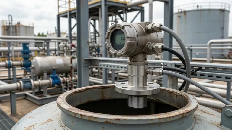
In the landscape of industrial automation, the requirement for precise, non-contact level measurement is a cornerstone of operational efficiency. Whether managing a single water storage tank or a complex chemical processing line, the deployment of 1 ultrasonic meter can provide the critical data necessary for inventory management, process control, and safety monitoring. As a professional manufacturer, Welk specializes in delivering robust Ultrasonic Level Meters designed to withstand the rigors of diverse industrial environments.
This guide serves as a practical engineering reference for selecting, installing, and maintaining ultrasonic level technology. By understanding the underlying physics and the specific technical requirements of your application, you can ensure that your measurement solution remains accurate and reliable over its entire service life.
Understanding the Principles of Ultrasonic Level Measurement
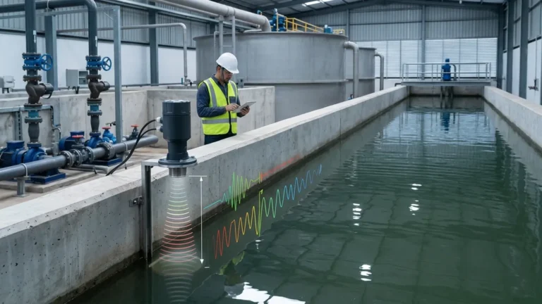
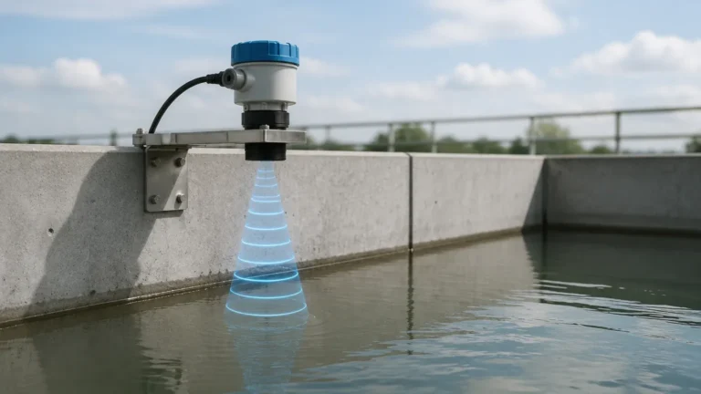
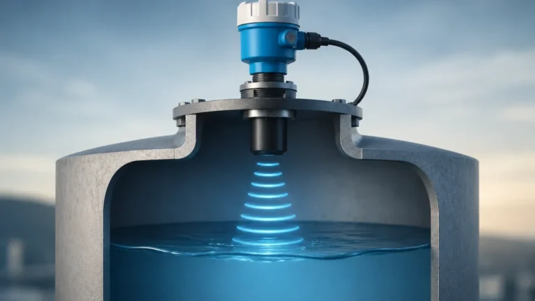
Before selecting an instrument, it is essential to understand how ultrasonic technology functions. Ultrasonic level meters operate on the "Time-of-Flight" (ToF) principle. The device features a transducer, typically containing a piezoelectric crystal, which emits high-frequency sound pulses (usually between 20 kHz and 200 kHz).
The Measurement Cycle
1. Emission: The transducer generates a sound wave that travels through the air or gas space toward the surface of the medium.
2. Reflection: When the sound wave hits the surface of the liquid or solid, a portion of the energy is reflected back toward the sensor as an echo.
3. Detection: The transducer receives the returning echo and converts the mechanical energy back into an electrical signal.
4. Calculation: The internal microprocessor measures the time elapsed between emission and reception. Using the known speed of sound in air (approximately 340 m/s at 20°C), the meter calculates the distance to the product surface.
The formula used is:
Distance = (Speed of Sound × Time) / 2
By subtracting this distance from the total height of the vessel (the "tank height" or "zero point"), the meter determines the actual level of the material. When configuring 1 ultrasonic meter, the user must input these physical dimensions into the device's software to ensure the output signal (such as 4-20mA or Modbus) correctly reflects the volume or level.
Technical Specifications for a 1 Ultrasonic Meter Deployment
When evaluating a single ultrasonic unit for a project, several technical parameters must be scrutinized to ensure compatibility with the process. Unlike contact-based methods, ultrasonic meters are sensitive to the environment through which the sound travels.
Measurement Range and Blocking Distance
Every ultrasonic sensor has a defined measurement range, typically spanning from 0.1 meters to 30 meters (approx. 0.33 ft to 98 ft). A critical factor often overlooked is the blocking distance (also known as the "dead zone"). This is the area immediately below the transducer face where the device cannot accurately measure because the crystal is still vibrating from the emission pulse when the echo returns. For a standard 1 ultrasonic meter setup, the blocking distance usually ranges from 0.2 meters to 0.6 meters (0.66 ft to 1.97 ft). If the liquid level enters this zone, the meter will provide erratic readings or a "full" error signal.
Accuracy and Resolution
Industrial-grade ultrasonic meters typically offer an accuracy of ±0.25% to ±0.5% of the measured range. Resolution—the smallest change in level the meter can detect—is often as fine as 1 mm (0.039 in). These specs are contingent on proper temperature compensation, as the speed of sound varies with air temperature. Quality instruments include an integrated temperature sensor to adjust calculations in real-time.
Selection Criteria: Choosing the Right Instrument
Selecting the appropriate hardware requires a thorough review of the application's physical and chemical properties. The following table outlines the primary considerations when choosing between different configurations of Ultrasonic Level Meters.
| Feature | Integrated (Compact) Type | Remote (Split) Type |
| :— | :— | :— |
| Configuration | Sensor and electronics in one housing. | Sensor and display/controller are separate. |
| Installation | Easier to install; requires only one mounting point. | Better for hazardous areas or high-vibration sites. |
| Wiring | Direct connection to PLC/SCADA. | Requires shielded cable between sensor and controller. |
| Maintenance | Access required at the top of the tank. | Display can be mounted at eye level for easy reading. |
| Best For | Standard water tanks, sumps, and simple pits. | Tall silos, aggressive chemicals, or remote monitoring. |
Material Compatibility
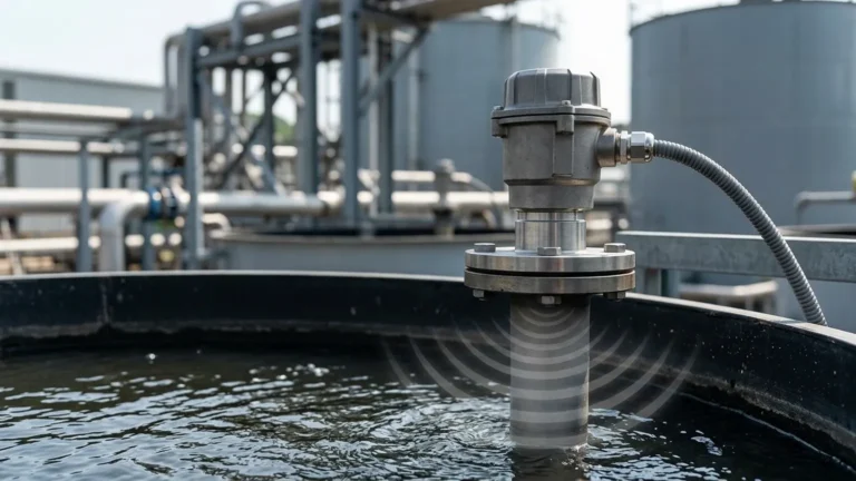
The transducer face is the only part of the meter exposed to the tank atmosphere. For water treatment, standard ABS or PVC housings are sufficient. However, for chemical applications involving acids or bases, PVDF (Polyvinylidene fluoride) or PTFE (Teflon) coatings are necessary to prevent corrosion. When specifying 1 ultrasonic meter, always confirm the chemical compatibility of the wetted materials with the process vapors.
Practical Installation Guidelines for Optimal Performance
Even the most advanced ultrasonic meter will fail if installed incorrectly. To maximize signal strength and minimize noise, follow these engineering best practices:
1. Perpendicular Alignment: The transducer face must be perfectly parallel to the liquid surface. A tilt of even a few degrees can cause the reflected signal to bounce away from the sensor, leading to "Lost Echo" errors.
2. Avoid the "Center" of Domed Tanks: In tanks with domed or parabolic tops, do not mount the sensor in the exact center. The shape of the roof can act as a parabolic dish, concentrating multiple reflections and creating false echoes.
3. Clear the Beam Path: The ultrasonic pulse spreads out in a cone shape (typically 5° to 12° beam angle). Ensure there are no obstructions within this cone, such as ladders, pipes, or agitator blades. If obstructions are unavoidable, many modern meters offer "False Echo Suppression" software to ignore these static reflections.
4. Inflow Protection: Position the meter away from the tank's fill inlet. Falling liquid creates turbulence and foam, both of which scatter the sound waves and degrade measurement accuracy.
5. Standpipe Considerations: If mounting on a standpipe or nozzle, ensure the pipe's inner surface is smooth and free of burrs. The nozzle height should be kept as short as possible to prevent interference with the ultrasonic cone near the transducer face.

Environmental Factors and Operational Limitations
While ultrasonic technology is versatile, it is not a universal solution. Engineers must be aware of specific conditions that can impede the performance of 1 ultrasonic meter.
Foam and Turbulence
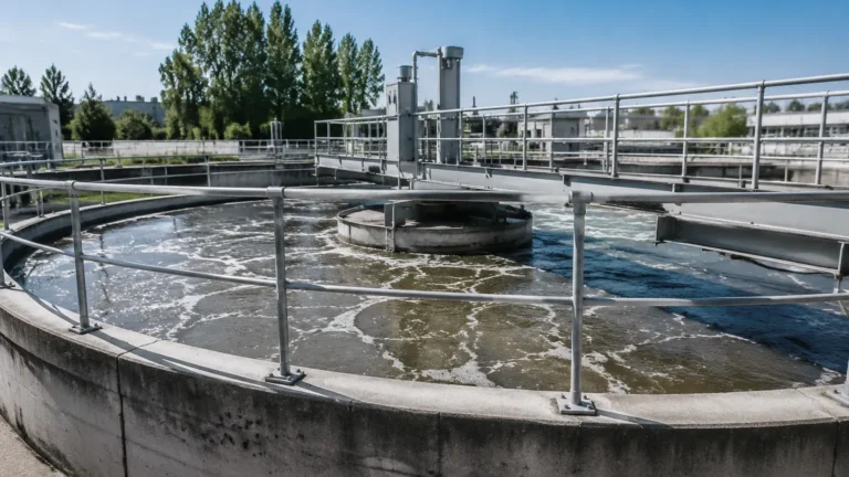
Heavy foam on the surface of a liquid acts as an acoustic insulator, absorbing the sound pulse rather than reflecting it. If your process involves significant foaming (common in some wastewater treatment or chemical mixing), a radar level meter or a hydrostatic transmitter may be a more reliable choice. Light turbulence is generally manageable, but extreme surface agitation can scatter the signal.
Pressure and Vacuum
Ultrasonic waves require a medium (air or gas) to travel. Therefore, these meters cannot function in a vacuum. Furthermore, high-pressure environments change the density of the gas, which significantly alters the speed of sound. Most standard ultrasonic level meters are rated for atmospheric pressure or slight overpressure (up to 0.3 MPa / 3 bar).
Vapor and Dust
Dense steam, heavy dust, or high concentrations of solvent vapors can attenuate the ultrasonic signal. In applications like hot water storage or grain silos, the signal may be weakened to the point where the meter loses track of the level. In these instances, high-power transducers or alternative technologies like guided wave radar are recommended.
Maintenance and Calibration Protocols
One of the primary advantages of utilizing 1 ultrasonic meter is the low maintenance requirement due to the lack of moving parts. However, a routine inspection schedule is recommended to ensure long-term reliability.
* Visual Inspection: Periodically check the transducer face for the buildup of condensation, dust, or crystallized chemicals. A clean face is essential for clear signal transmission.
* Verification: Use a manual tape measure to verify the meter's reading against the actual level. This should be done at multiple points (e.g., 25%, 50%, and 75% of tank capacity) to ensure linearity.
* Firmware Updates: Manufacturers often release software updates that improve signal processing algorithms. Ensure your device is running the latest version provided by the factory.
Frequently Asked Questions (FAQ)
Q: Can 1 ultrasonic meter measure the level of solids?
A: Yes, but with limitations. Solids like grain, sand, or plastic pellets do not reflect sound as efficiently as liquids. Additionally, solids often form a conical pile rather than a flat surface. You must select a meter specifically rated for solids, which usually features a more powerful transducer and specialized signal processing.
Q: How do I handle measurement in a narrow tank?
A: For narrow tanks, select a meter with a narrow beam angle (e.g., 5°). This keeps the ultrasonic energy concentrated and prevents the signal from hitting the tank walls, which could cause false readings.
Q: What happens if the temperature changes rapidly?
A: Rapid temperature fluctuations can create temperature gradients in the air space. While integrated temperature compensation helps, it only measures the temperature at the sensor head. In extreme cases, an external temperature sensor placed midway down the tank can provide more accurate data for the compensation algorithm.
Q: Is it possible to use 1 ultrasonic meter for open channel flow?
A: Absolutely. By installing the meter over a flume or weir and using a controller with built-in flow formulas (like Parshall or Rectangular weir equations), the level measurement can be converted into a highly accurate flow rate (e.g., liters per second).
Conclusion
Implementing 1 ultrasonic meter is a cost-effective and reliable way to achieve non-contact level monitoring across a wide range of industrial applications. By prioritizing correct installation, understanding the physical constraints of the technology, and selecting the appropriate material specifications, engineers can ensure high-performance data acquisition. For those seeking advanced features and industrial-grade durability, exploring the range of Ultrasonic Level Meters from Welk provides a path toward optimized process automation and improved safety standards.