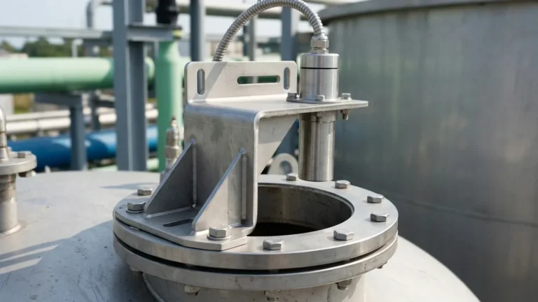
Ultrasonic Level Sensor Specifications
Comprehensive Guide to Ultrasonic Level Sensor Specifications
In industrial process control, selecting the correct instrumentation is critical for operational efficiency and safety. Among the various technologies available, Ultrasonic Level Meters have become a standard solution for non-contact level measurement in water treatment, chemical processing, and industrial automation. Understanding the detailed ultrasonic level sensor specifications is essential for engineers and procurement professionals to ensure the chosen device meets the specific demands of their application.
This guide examines the technical parameters of ultrasonic technology, providing a practical framework for evaluating performance, installation requirements, and environmental limitations.
Understanding the Measurement Principle
Before diving into specific technical data, it is important to understand the physics governing these instruments. Ultrasonic level measurement is based on the "Time of Flight" (ToF) principle.
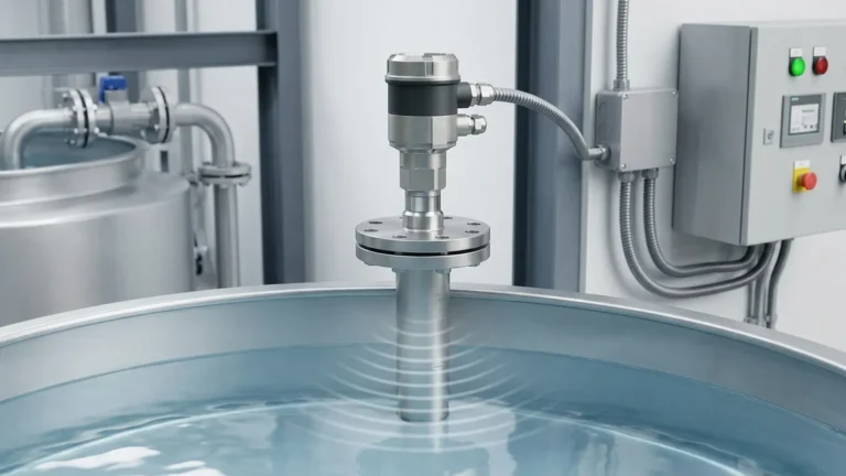
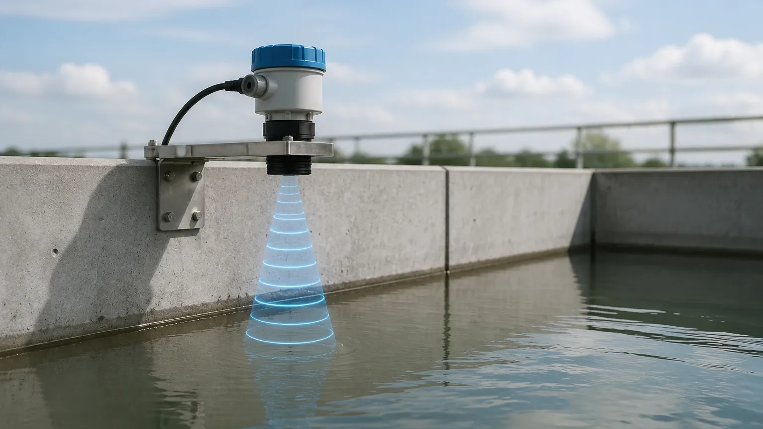
The sensor's transducer emits a high-frequency acoustic pulse toward the surface of the medium (liquid or solid). This sound wave travels through the air, hits the surface, and is reflected back as an echo to the transducer. The device's internal electronics measure the time interval between the pulse emission and the echo reception.
Using the known speed of sound in air (approximately 343 m/s at 20°C), the distance is calculated using the formula:
Distance = (Speed of Sound × Time) / 2
By subtracting this distance from the total height of the tank (the "zero point"), the device determines the actual level of the material. Because the speed of sound varies with air temperature, high-quality Ultrasonic Level Meters include integrated temperature sensors to compensate for these changes automatically, ensuring consistent accuracy.
Key Technical Specifications for Selection
When reviewing a datasheet, several core specifications dictate whether a sensor is suitable for a specific tank or process. Below are the primary parameters to evaluate.
1. Measuring Range
Range specifies the minimum and maximum distances the sensor can reliably measure. Industrial sensors typically offer ranges from 0.3 meters up to 30 meters. It is crucial to select a sensor where the expected level fluctuations fall comfortably within the middle 80% of the rated range to account for unforeseen process upsets.
2. The Dead Zone (Blocking Distance)
The "Dead Zone" is a critical specification. It refers to the area directly beneath the transducer face where the sensor cannot receive an echo because it is still vibrating from the pulse emission. If the liquid level enters this zone, the sensor will provide an error or an incorrect reading. Typical dead zones range from 0.2m to 0.6m depending on the frequency of the transducer.
3. Beam Angle
The beam angle defines the conical spread of the ultrasonic pulse. A narrower beam angle (e.g., 5° to 8°) is generally preferred because it focuses the energy on the target and reduces the risk of "false echoes" from tank walls, internal ladders, or agitators. Wider beam angles (10° to 12°) may be acceptable in large, open basins but require careful placement in confined vessels.
4. Transducer Frequency
Frequency is inversely proportional to range.
* High Frequency (60 kHz – 80 kHz): Used for shorter ranges (0-5m). These offer higher resolution and smaller dead zones.
* Low Frequency (20 kHz – 40 kHz): Used for long-range applications (up to 30m) as lower frequencies penetrate dust and steam more effectively and lose less energy over distance.
Performance Parameters and Accuracy
Accuracy in ultrasonic level sensor specifications is usually expressed as a percentage of the measured distance or the full scale (FS).
| Specification | Typical Industrial Standard |
| :— | :— |
| Accuracy | ±0.25% to ±0.5% of full range |
| Resolution | 1 mm to 3 mm |
| Update Rate | < 200 ms |
| Temperature Compensation | Automatic, via internal NTC/PT100 |
Accuracy is heavily influenced by environmental factors. For instance, if a tank contains heavy vapors or significant temperature gradients, the speed of sound changes, which can introduce errors if not properly compensated. Welk instruments utilize advanced algorithms to filter out noise and prioritize the true surface echo, maintaining high precision even in turbulent conditions.
Environmental and Material Specifications
Industrial environments subject sensors to harsh conditions. The physical build of the sensor must be compatible with the chemical and physical properties of the site.
* Housing Materials: Common options include ABS, PVC, or PVDF for chemical resistance. For hazardous areas, explosion-proof aluminum or stainless steel housings are required.
* Ingress Protection (IP Rating): Most outdoor or wash-down applications require at least IP66 or IP67. Submersible versions are rated IP68.
* Process Temperature: Standard sensors operate between -20°C and +60°C. Specialized high-temperature versions can reach up to 80°C, but beyond this, the air density changes significantly, often requiring a transition to radar technology.
* Process Pressure: Ultrasonic sensors are generally designed for atmospheric pressure. Because sound requires a medium to travel, they cannot function in a vacuum. High-pressure environments (above 0.3 MPa) can also distort the acoustic signal.
Practical Selection Table
Use the following table to align your application requirements with typical ultrasonic level sensor specifications.
| Application Type | Recommended Range | Beam Angle | Output Requirement |
| :— | :— | :— | :— |
| Small Chemical Tote | 0.25m – 4m | Narrow (<8°) | 4-20mA / RS485 |
| Water Treatment Basin | 0.5m – 12m | Standard (10°) | 4-20mA + Relays |
| Deep Sump/Well | 1m – 20m | Narrow (<6°) | Modbus RTU |
| Grain/Solid Silo | 1m – 15m | Wide (12°) | High-power Pulse |
Installation Best Practices
Even the highest-specification sensor will fail if installed incorrectly. To ensure the reliability of your Ultrasonic Level Meters, follow these engineering guidelines:
1. Perpendicular Alignment: The transducer face must be perfectly parallel to the liquid surface. A tilt of even a few degrees can cause the reflected signal to miss the receiver.
2. Avoid the Fill Stream: Never mount the sensor directly above the point where liquid enters the tank. The turbulence and entrained air will scatter the ultrasonic signal.
3. Distance from Walls: Mount the sensor at a distance from the wall at least 1/6th of the tank height to prevent side-wall interference.
4. Standpipe Usage: If the tank has foam or heavy turbulence, installing the sensor inside a plastic standpipe (stilling well) can provide a calm surface for measurement. However, the pipe must be smooth and have a vent hole at the top.
Limitations and Prohibitions
While versatile, ultrasonic technology is not a universal solution. Engineers should avoid specifying ultrasonic sensors in the following scenarios:
* Vacuum Applications: Sound cannot travel in a vacuum. Radar or hydrostatic transmitters should be used instead.
* Heavy Foam: Thick, protein-based foam absorbs ultrasonic pulses rather than reflecting them, leading to a "Loss of Echo" error.
* High Dust Environments: While low-frequency sensors can handle some dust, extreme dust (like cement filling) can attenuate the signal.
* High Pressure/High Temp: Applications exceeding 80°C or significant pressure should utilize Radar technology, which is unaffected by gas layer density changes.
Frequently Asked Questions (FAQs)
Q: How does wind affect ultrasonic level measurement?
A: In outdoor applications, strong winds can "blow" the acoustic pulse away from the transducer, especially over long distances (over 10m). In these cases, using a sunshade or a protective shroud is recommended.
Q: Can ultrasonic sensors measure solids?
A: Yes, but the range is typically reduced by 50% compared to liquids. Solids like grain or coal have an "angle of repose" which reflects the sound away from the sensor. Higher-power transducers are required for these applications.
Q: What is the difference between 2-wire and 4-wire specifications?
A: 2-wire sensors are loop-powered (the signal and power share the same wires), which is easier to install but provides less power to the transducer. 4-wire sensors have separate power supplies, allowing for higher-intensity pulses and longer measurement ranges.
Conclusion
Evaluating ultrasonic level sensor specifications requires a balance between the physical constraints of the installation site and the performance requirements of the process. By focusing on the dead zone, beam angle, and environmental compatibility, engineers can implement a reliable, non-contact measurement solution that reduces maintenance costs and improves data accuracy.
For complex applications involving corrosive chemicals or long-range requirements, consulting with a manufacturer like Welk ensures that the instrument's features—such as advanced false-echo suppression and automatic temperature compensation—are correctly matched to the operational environment.