3 Ultrasonic Meter
3 Ultrasonic Meter
In the realm of industrial process control, the term "3 ultrasonic meter" typically refers to one of two critical specifications: a device with a 3-meter (approx. 9.8 ft) measurement range or a 3-wire electrical configuration. Both interpretations are vital for engineers designing level monitoring systems for water treatment, chemical storage, and industrial automation.
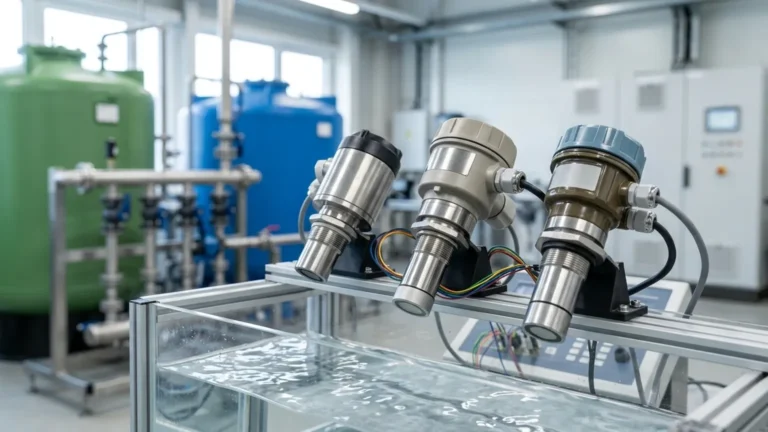
Selecting the right Ultrasonic Level Meters requires a deep understanding of how sound waves interact with the environment and the electrical requirements of the local control system. This guide provides a factual technical overview of these instruments, their principles, and practical application strategies.
Understanding the Measurement Principle
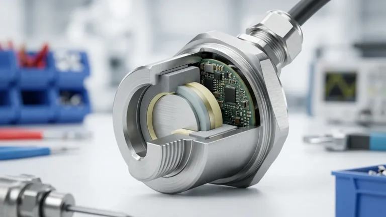
Ultrasonic level measurement is a non-contact technology based on the "Time of Flight" (ToF) principle. The instrument's transducer emits a high-frequency ultrasonic pulse—usually between 20 kHz and 80 kHz—which travels through the air, reflects off the surface of the medium (liquid or solid), and returns to the sensor.
The Calculation Logic
The meter calculates the distance ($D$) between the sensor face and the material surface using the following formula:
$$D = \frac{c \times t}{2}$$
Where:
* $c$ is the speed of sound in the medium (typically air).
* $t$ is the elapsed time between emission and reception.
Because the speed of sound is influenced by air temperature (increasing by approximately 0.6 m/s for every 1°C rise), professional-grade ultrasonic level meters include integrated temperature sensors to compensate for these fluctuations, ensuring accuracy remains within 0.25% to 0.5% of the measured range.
The Significance of the "3" in Ultrasonic Meters
When a project specification calls for a "3 ultrasonic meter," it usually targets one of the following two technical requirements:
1. 3-Meter Measurement Range
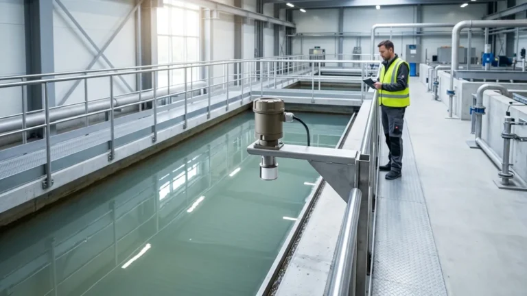
A 3-meter range is a standard specification for small-scale process tanks, chemical totes, and open-channel flow monitoring. Instruments optimized for this range typically operate at higher frequencies (60 kHz to 80 kHz).
* Advantages: Higher frequencies allow for a smaller "blind zone" (the area immediately below the sensor where measurement is impossible) and a narrower beam angle, which helps avoid reflections from tank walls or internal obstructions.
* Typical Applications: Sumps, IBC tanks, and small reagent vessels.
2. 3-Wire Electrical Configuration
In industrial wiring, a 3-wire configuration consists of a positive power lead, a negative/common lead, and a dedicated signal output lead (usually 4-20mA or 0-10V).
* Versus 2-Wire: While 2-wire (loop-powered) sensors are common for their simplicity, 3-wire sensors are often preferred when the device requires more power to drive a stronger ultrasonic pulse or to power an integrated backlit display and local relays.
* Power Supply: Typically 24V DC. The 3-wire setup ensures that the signal integrity is not compromised by the power requirements of the transducer's internal electronics.
Technical Selection Criteria
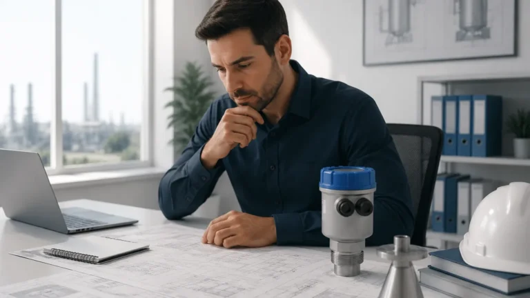
Choosing the correct ultrasonic meter involves more than just matching the range. Engineers must evaluate the physical properties of the medium and the vessel geometry.
Selection Comparison Table
| Feature | 3m Compact Sensor | 10m Standard Sensor | 30m Long-Range Sensor |
| :— | :— | :— | :— |
| Ultrasonic Frequency | 60–80 kHz | 40 kHz | 20 kHz |
| Blind Zone (Dead Band) | 0.20m – 0.25m | 0.35m – 0.5m | 0.8m – 1.2m |
| Beam Angle | 5° – 8° | 10° – 12° | 15° |
| Resolution | 1 mm | 2 mm | 10 mm |
| Best Use Case | Chemical Totes | Water Reservoirs | Large Grain Silos |
Material Compatibility
The housing and transducer face material must be compatible with the process environment. For corrosive chemicals, PVDF (Polyvinylidene Fluoride) or PTFE (Polytetrafluoroethylene) transducers are recommended. Standard water and wastewater applications often utilize ABS or PP (Polypropylene) housings.
Installation Considerations and Best Practices
Proper installation is the most critical factor in ensuring the reliability of an ultrasonic level meter. Even the most advanced sensor will fail if the acoustic path is compromised.
1. Avoid the Blind Zone: The sensor must be mounted at a height where the maximum liquid level never enters the blind zone (e.g., 0.25m for a 3m sensor). If the liquid enters this zone, the meter may report an incorrect "full" or "empty" status.
2. Perpendicular Alignment: The transducer face must be perfectly parallel to the liquid surface. A tilt of even a few degrees can cause the reflected signal to miss the receiver, leading to a "Loss of Echo" (LOE) error.
3. Wall Distance: To prevent false echoes from the tank wall, the sensor should be installed at a distance of at least 200mm from the wall for every 1 meter of depth, depending on the beam angle.
4. Stay Clear of Inflow: Do not install the sensor directly above the fill stream. The turbulence and air entrainment from the incoming liquid will scatter the ultrasonic pulse.
5. Obstruction Mapping: If the tank has internal ladders, pipes, or agitators, select a meter with "False Echo Suppression" software. This allows the user to program the meter to ignore fixed reflections at specific distances.

Limitations and Environmental Factors
While ultrasonic level meters are versatile, they are not suitable for every application. Engineers should be aware of the following limitations:
* Vacuum Conditions: Ultrasonic waves require a medium (air or gas) to travel. They cannot function in a vacuum.
* Heavy Foam: Thick, dense foam absorbs the ultrasonic pulse rather than reflecting it. In these cases, a radar level meter or a hydrostatic transmitter is a better choice.
* High Pressure/Temperature: Extreme pressure changes the density of the air, affecting the speed of sound beyond what standard temperature compensation can handle. Most ultrasonic sensors are limited to 2 bar (approx. 29 psi) and temperatures below 80°C.
* Dust and Vapor: While light dust is manageable, extremely heavy dust or thick steam can attenuate the signal. For 3-meter applications with heavy steam, a 3-wire sensor with a high-power pulse is often necessary to penetrate the vapor.
Maintenance and Troubleshooting
Ultrasonic meters are generally low-maintenance due to their non-contact nature. However, periodic checks are recommended:
* Transducer Cleaning: In high-humidity or splashing environments, condensation or material buildup can occur on the sensor face. Wipe the transducer periodically with a soft cloth and mild detergent.
* Cable Integrity: Ensure that the cable entry is sealed with a proper gland to prevent moisture from entering the electronics housing, which is a common cause of failure in outdoor 3-wire installations.
* Signal Diagnostics: Modern meters provide an "Echo Profile" or signal strength indicator. If the signal strength drops below a certain threshold (e.g., 40dB), it may indicate that the sensor is misaligned or the medium surface has become too turbulent.
Frequently Asked Questions (FAQ)
Q: Can a 3m ultrasonic meter measure solids like sand or grain?
A: Yes, but the effective range is typically reduced by 50% because solids scatter the sound wave in different directions. For a 3-meter measurement of solids, a sensor rated for 6 or 10 meters is usually required.
Q: What is the difference between a 3-wire and a 4-wire ultrasonic meter?
A: A 3-wire system shares a common ground for power and signal. A 4-wire system has two dedicated wires for power (e.g., 110V/220V AC) and two isolated wires for the 4-20mA signal. 4-wire systems are typically used when AC power is the only source available.
Q: How do I handle a tank with an agitator?
A: Use a meter with a narrow beam angle and enable the "Agitator Avoidance" or "Time Filter" settings. This tells the software to ignore intermittent reflections caused by the moving blades and focus on the consistent reflection from the liquid surface.
For engineers seeking reliable, cost-effective solutions for process monitoring, Welk offers a range of industrial-grade Ultrasonic Level Meters designed for accuracy and durability. Whether your application requires a compact 3-meter range or a robust 3-wire configuration for integrated automation, understanding these technical boundaries ensures long-term operational success.