2 Ultrasonic
2 Ultrasonic
In the landscape of industrial automation, ultrasonic technology remains a cornerstone for non-contact level measurement. When engineers discuss "2 ultrasonic" configurations, they are typically referring to 2-wire, loop-powered ultrasonic transmitters—a standard in modern process control due to their efficiency and ease of integration. As a professional manufacturer, Welk provides a range of these instruments designed to meet the rigorous demands of water treatment, chemical processing, and oil and gas industries.
This guide provides a comprehensive technical overview of Ultrasonic Level Meters, focusing on the 2-wire (2 ultrasonic) architecture, its measurement principles, selection criteria, and practical installation requirements for industrial applications.
1. Measurement Principles of Ultrasonic Technology
Before selecting a specific 2 ultrasonic device, it is essential to understand the underlying physics. Ultrasonic level meters operate on the Time-of-Flight (ToF) principle.
The Transducer Mechanism
The heart of the instrument is a piezoelectric transducer. When energized, the transducer vibrates at a high frequency (typically between 20 kHz and 70 kHz), emitting a burst of sound waves toward the material surface. These waves travel through the air or gas space above the medium, reflect off the surface, and return to the transducer.
Distance Calculation
The sensor acts as both a transmitter and a receiver. The internal electronics measure the time interval between the emission of the pulse and the reception of the echo. The distance ($D$) from the sensor face to the material surface is calculated using the formula:
$$D = \frac{c \times t}{2}$$
Where:
* $c$: The speed of sound in the medium (typically air, approx. 344 m/s at 20°C).
* $t$: The measured time for the round trip.
By knowing the total height of the tank ($H$), the device calculates the actual level ($L$) as $L = H – D$. In 2-wire systems, this calculated value is converted into a 4-20mA analog signal, often with a superimposed digital HART signal for advanced diagnostics.
2. Understanding the "2" in 2 Ultrasonic: 2-Wire vs. 4-Wire
The term "2 ultrasonic" primarily distinguishes loop-powered instruments from their 4-wire counterparts. Understanding this distinction is critical for electrical design and power budgeting.
2-Wire (Loop-Powered) Systems
In a 2-wire configuration, the same pair of wires provides the power supply (typically 24V DC) and carries the 4-20mA output signal.
* Power Consumption: The device must operate within a very tight power budget, as it cannot draw more than 3.5mA to 4mA for its internal processing to ensure the 4mA floor of the signal remains accurate.
* Wiring Efficiency: Significant cost savings are realized in cabling and installation labor, as only one shielded twisted pair is required.
4-Wire (Separate Power) Systems
4-wire systems use two wires for power (AC or DC) and two separate wires for the 4-20mA signal.
* Power Availability: These units have more energy available for high-power transducers, which is necessary for very long ranges (e.g., over 30 meters) or for penetrating heavy dust and steam.
* Complexity: They require more extensive wiring and are generally used only when the limitations of 2-wire technology cannot be overcome.
3. Key Evaluation Criteria for 2 Ultrasonic Selection
Selecting the right Ultrasonic Level Meters requires an analysis of the process environment. While 2-wire units are versatile, they are subject to specific operational boundaries.
Measurement Range and Dead Zone
Every ultrasonic sensor has a "dead zone" (or blocking distance) directly beneath the transducer face. In this zone, the sensor cannot receive an echo because it is still vibrating from the transmission pulse. Typical dead zones range from 0.2m to 0.5m. If the tank is filled into this zone, the meter will provide an error or an incorrect reading.
Media Characteristics
* Liquids: Ideal for ultrasonic measurement, provided they do not foam excessively. Foam absorbs the sound pulse, leading to signal loss.
* Solids: Measuring grain, sand, or powders is more challenging. The irregular surface of solids scatters the sound waves, and the angle of repose can direct the echo away from the sensor. For these applications, a higher-power 2 ultrasonic transmitter with a narrower beam angle is often required.
Environmental Factors
* Temperature: The speed of sound varies with temperature ($c \approx 331.5 + 0.6T$). Welk ultrasonic meters include integrated temperature sensors to automatically compensate for these changes. However, if there is a significant temperature gradient in the tank, accuracy may be affected.
* Pressure: Ultrasonic meters are generally limited to near-atmospheric pressure. High pressure increases the density of the gas, while vacuum prevents sound waves from traveling entirely.
4. Practical Selection Table
The following table assists in determining the appropriate configuration for common industrial scenarios.
| Feature | 2-Wire (2 Ultrasonic) | 4-Wire High Power |
| :— | :— | :— |
| Power Supply | 24V DC (Loop-powered) | 24V DC, 110V/220V AC |
| Max Range (Liquid) | Up to 15-20 meters | Up to 40+ meters |
| Max Range (Solid) | Up to 7-10 meters | Up to 20+ meters |
| Installation Cost | Low (Minimal wiring) | Moderate (Dual cable runs) |
| Signal Output | 4-20mA, HART | 4-20mA, RS485, Relays |
| Common Use Case | Water tanks, chemical sumps | Large silos, deep wells, steam |

5. Installation Considerations and Best Practices
Correct installation is the most critical factor in the performance of 2 ultrasonic instruments. Poor placement is responsible for over 80% of field failures.
Positioning and Obstructions
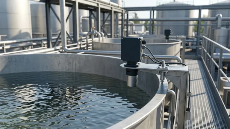
* Avoid the Center: Do not mount the sensor in the center of a circular tank. This can cause "multiple echoes" as the sound waves reflect off the walls and converge in the center, leading to false readings.
* Clear Path: Ensure there are no ladders, pipes, or agitators within the ultrasonic beam. The beam spreads as it travels; a typical beam angle is 5° to 12°.
* Distance from Wall: The sensor should be mounted at least 200mm to 500mm away from the tank wall to prevent side-wall interference.
Mounting Orientation
* Perpendicularity: The transducer face must be perfectly parallel to the liquid surface. A tilt of even a few degrees can cause the reflected signal to miss the receiver.
* Nozzle Length: If mounting on a nozzle or standpipe, the nozzle must be as short and wide as possible. If the nozzle is too long, the sound pulse will reflect off the inside of the pipe before reaching the tank, creating a false "high level" signal.
Environmental Shielding
For outdoor installations, a sunshade is recommended. Direct sunlight can heat the sensor body to temperatures much higher than the ambient air, causing the internal temperature compensation to fail and resulting in significant measurement errors.
6. Technical Limitations and Common Risks
While highly effective, 2-wire ultrasonic technology is not a universal solution. Engineers must be aware of the following limitations:
1. Vapor and Heavy Steam: Certain chemicals produce vapors that change the density of the air, altering the speed of sound and causing errors. In cases of heavy steam, the water droplets can attenuate the signal entirely.
2. Vacuum Applications: Sound cannot travel in a vacuum. If the process involves a full vacuum, a radar level meter or hydrostatic transmitter should be used instead.
3. Agitation and Turbulence: Heavy turbulence on the liquid surface will scatter the echo. While software filtering can mitigate some of this, extreme cases may require a stilling well or a different technology.
7. Frequently Asked Questions (FAQ)
Q: Can a 2-wire ultrasonic meter be used for hazardous areas?
A: Yes. Most 2-wire (2 ultrasonic) transmitters are designed for Intrinsic Safety (IS). Because they operate on low power, they can be used in Zone 0 or Zone 1 environments when paired with an appropriate safety barrier.
Q: How do I handle foam on the surface of the liquid?
A: Light, airy foam can often be ignored by the sensor, but thick, dense foam will absorb the signal. If foam is a constant factor, consider using a Welk radar level meter or a magnetic level gauge.
Q: What is the maximum cable length for a 2-wire system?
A: Since it is a 4-20mA current loop, the cable can typically run up to 1,000 meters, depending on the wire gauge and the total loop resistance (including the input impedance of the PLC/controller).
Q: Does the 2 ultrasonic meter require calibration?
A: Most modern units come pre-calibrated. However, "field mapping" or "false echo suppression" is often required during commissioning to tell the sensor to ignore fixed internal obstructions like pipes or brackets.
8. Conclusion and Next Steps
The transition to 2-wire ultrasonic technology offers a balance of precision, reliability, and cost-effectiveness. For most standard industrial liquid applications, a 2 ultrasonic transmitter is the most efficient choice for non-contact measurement. When specifying these units, it is vital to confirm the tank geometry, the chemical compatibility of the transducer face (typically PVDF or PTFE), and the potential for environmental interference.
For engineers looking to integrate these solutions into their process automation systems, it is recommended to Review product options and application support to ensure the selected hardware aligns with the specific acoustic and electrical requirements of the facility. By following the installation and selection guidelines outlined in this reference, users can achieve long-term, maintenance-free level monitoring in even the most demanding B2B environments.