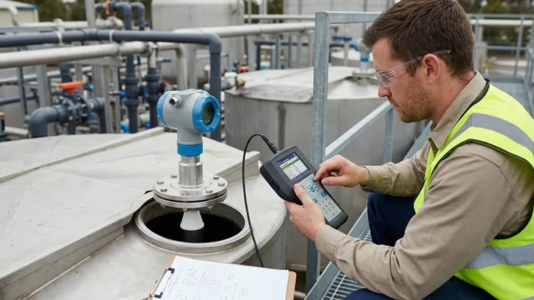
2 Ultrasonic Meter
2 Ultrasonic Meter
In the field of industrial automation, selecting the correct instrumentation requires a balance between accuracy, installation complexity, and cost-effectiveness. When engineers discuss a "2 ultrasonic meter," they are typically referring to one of two critical specifications: a 2-wire (loop-powered) wiring configuration or a sensor optimized for a 2-meter (approx. 6.5 ft) measurement range.
Both interpretations represent essential segments of the level measurement market. 2-wire ultrasonic level meters are favored for their simplified integration into existing 4-20mA control loops, while short-range sensors are vital for small chemical tanks, dosing systems, and open-channel flow monitoring. This guide examines the technical principles, selection criteria, and installation best practices for these instruments to ensure reliable performance in process environments.
Understanding the Measurement Principle
Ultrasonic Level Meters operate on the Time-of-Flight (ToF) principle. The instrument’s transducer acts as both a transmitter and a receiver. It emits a high-frequency acoustic pulse—usually between 20 kHz and 80 kHz—that travels through the air gap toward the material surface.
When the pulse hits the surface of the liquid or solid, it is reflected back to the transducer as an echo. The meter’s internal microprocessor calculates the distance ($D$) based on the speed of sound in air ($c$) and the time elapsed ($t$) between transmission and reception:
$$D = \frac{c \times t}{2}$$
The level of the material is then determined by subtracting this distance from the total height of the vessel (the tank zero point). Because this is a non-contact method, the sensor remains unaffected by the chemical properties of the medium, such as corrosiveness or viscosity, provided the surface is reflective and the atmosphere is conducive to sound transmission.
The Significance of "2" in Ultrasonic Instrumentation
In a B2B procurement context, the term "2 ultrasonic meter" most frequently relates to the electrical interface or the physical measurement range.
1. 2-Wire (Loop-Powered) Configuration
A 2-wire ultrasonic meter uses the same pair of wires for both power supply and signal transmission (4-20mA). This configuration is the industry standard for modern digital plants.
* Efficiency: It reduces cabling costs by 50% compared to traditional 4-wire systems.
* Integration: It is compatible with standard PLC and DCS analog input cards that provide loop power (typically 24V DC).
* Power Management: These units are engineered for extremely low power consumption, operating on as little as 3.8mA to 4mA for the internal electronics.
2. 2-Meter Measurement Range
For applications involving small process vessels, sumps, or IBCs (Intermediate Bulk Containers), a sensor optimized for a 2-meter range is often preferred. While many industrial sensors can measure up to 10 or 15 meters, a dedicated short-range sensor often features a higher frequency transducer. Higher frequencies result in a smaller "dead zone" (the area directly beneath the sensor where measurement is impossible) and better resolution for small-scale changes in level.
Technical Selection Criteria
Choosing between a 2-wire loop-powered meter and a 4-wire line-powered meter depends on the power availability and the required signal strength. Below is a comparison table to assist in the selection process.
Table 1: Comparison of 2-Wire vs. 4-Wire Ultrasonic Systems
| Feature | 2-Wire (Loop-Powered) | 4-Wire (Line-Powered) |
| :— | :— | :— |
| Power Supply | 24V DC (via signal loop) | 24V DC, 110V AC, or 220V AC |
| Wiring Complexity | Low (2 cores) | Moderate (4 cores) |
| Signal Strength | Standard | High (better for dust/steam) |
| Output Options | 4-20mA, HART | 4-20mA, Relays, RS485, Modbus |
| Typical Range | 0.25m to 12m | 0.25m to 30m+ |
| Installation Cost | Lower | Higher |
When specifying a 2 ultrasonic meter for a project, engineers must also confirm the chemical compatibility of the transducer face. Common materials include PVDF for corrosive acids or Polypropylene (PP) for general water treatment applications.
Practical Installation Considerations
To ensure the accuracy of an ultrasonic level meter, the physical installation must account for the physics of sound. Failure to follow these guidelines often results in "lost echoes" or false high-level readings.
1. The Dead Zone (Blocking Distance)
Every ultrasonic sensor has a dead zone, typically ranging from 0.2m to 0.5m (approx. 8 to 20 inches). If the liquid level rises into this zone, the meter will provide erratic data or a fixed error signal. For a 2-meter tank, a 0.25m dead zone represents 12.5% of the total capacity. If the tank must be filled to the very top, a mounting well or standpipe may be required to move the sensor further away from the maximum liquid level.
2. Beam Angle and Obstructions
The ultrasonic pulse spreads out in a cone, usually between 5° and 12°. Any internal tank structures—such as ladders, heating coils, or agitators—that enter this cone will create false reflections.
* Rule of Thumb: Install the sensor at a distance from the tank wall equal to at least 1/6th of the tank height.
* Alignment: The transducer face must be perfectly parallel to the liquid surface. Even a 2-degree tilt can significantly reduce the strength of the return echo in short-range applications.
3. Environmental Factors
Since the speed of sound varies with air temperature, all professional-grade Ultrasonic Level Meters include an integrated temperature sensor for automatic compensation. However, significant temperature gradients (e.g., a hot liquid in a cold tank) can still cause errors. In such cases, external temperature probes or radar technology may be more appropriate.
Limitations and Prohibitions
While highly versatile, ultrasonic technology is not a universal solution. Engineers should avoid using ultrasonic meters in the following scenarios:
* Vacuum Applications: Sound waves require a medium (air or gas) to travel. In a vacuum, the pulse cannot propagate.
* High Pressure: As pressure increases, the density of the gas changes, which can attenuate the signal and alter the speed of sound beyond the limits of standard compensation algorithms. Most ultrasonic meters are rated for atmospheric pressure or slightly above (up to 0.3 MPa).
* Heavy Foam: Surface foam acts as an acoustic absorber. If the foam is thick and dense, the pulse will be absorbed rather than reflected, leading to a loss of signal.
* Dusty Environments: While some high-power 4-wire units can handle moderate dust, heavy dust in silos can scatter the acoustic signal. Radar is generally preferred for solids with high dust content.
Maintenance and Troubleshooting
One of the primary benefits of the 2-wire ultrasonic meter is the lack of moving parts, which minimizes maintenance. However, periodic checks are recommended:
1. Transducer Cleaning: In applications with high humidity or splashing, condensate or material buildup may occur on the transducer face. This should be cleaned with a soft cloth and mild detergent; never use abrasive tools which could damage the matching layer.
2. Signal Strength Monitoring: Most modern meters provide a "Confidence" or "Echo Strength" value via the display or HART protocol. A steady decline in this value often indicates a need for cleaning or a change in process conditions (such as the onset of foaming).
3. Cable Integrity: For 2-wire systems, ensure the cable gland is tight to prevent moisture ingress into the electronic housing, which can cause loop failures.
Frequently Asked Questions (FAQ)
Q: Can a 2-wire ultrasonic meter drive a relay for pump control?
A: Typically, no. Because 2-wire meters are loop-powered, they do not have enough internal power to drive a mechanical relay coil. If you require local relay outputs, a 4-wire meter or a separate signal conditioner/controller is necessary.
Q: What is the maximum cable length for a 2-wire 4-20mA ultrasonic sensor?
A: This depends on the power supply voltage and the total loop resistance. With a standard 24V DC supply, cable runs of up to 1,000 meters (approx. 3,280 ft) are possible using shielded twisted-pair cabling.
Q: How does a 2-meter range sensor handle agitators?
A: Most units feature "False Echo Suppression" or "Echo Masking." During commissioning, the user can instruct the meter to ignore reflections at specific distances where agitator blades or other fixed obstructions are located.
Q: Is it possible to use an ultrasonic meter for fuel level measurement?
A: Yes, provided the sensor is intrinsically safe (Ex-rated) and the vapors do not significantly alter the speed of sound. For high-precision fuel custody transfer, however, hydrostatic or radar methods are often used.
Conclusion
Whether the requirement is for a 2-wire loop-powered interface or a 2-meter range capability, ultrasonic technology remains a cornerstone of industrial level measurement. By understanding the acoustic principles and respecting the physical limitations of the technology—such as the dead zone and beam angle—operators can achieve reliable, non-contact measurement in a wide variety of liquid and bulk solid applications. For complex environments involving high pressure or heavy foam, consulting with a technical specialist is recommended to determine if ultrasonic or alternative technologies like radar will provide the best long-term ROI.