8 Ultrasonic Flow Meter
8 Ultrasonic Flow Meter: Engineering Guide for Industrial Fluid and Level Control
In the landscape of industrial automation, precise fluid management requires a dual approach: monitoring the volume of liquid within a vessel and measuring the rate at which that liquid moves through the system. For engineers managing medium-to-large scale operations, the 8 ultrasonic flow meter (referring to the 8-inch or DN200 pipe size) represents a critical component in process efficiency. When integrated with advanced Ultrasonic Level Meters, these instruments provide a comprehensive view of hydraulic performance in water treatment, chemical processing, and oil and gas applications.
This guide examines the technical principles, selection criteria, and installation requirements for 8-inch ultrasonic flow measurement systems, emphasizing their synergy with level measurement technologies.
1. Measurement Principles: How Ultrasonic Technology Works
Ultrasonic measurement relies on the propagation of high-frequency sound waves through a medium. Depending on the application—whether measuring flow velocity in a pipe or the distance to a liquid surface in a tank—different physical principles are applied.
Transit-Time Principle (Flow)
Most industrial flow meters for 8-inch pipes utilize the transit-time method. This involves two transducers acting as both transmitters and receivers. They are mounted on the pipe at a specific distance. Sound pulses are sent upstream and downstream. Because the moving fluid carries the sound waves, the pulse traveling with the flow reaches the second transducer faster than the pulse traveling against it. This time difference (Δt) is directly proportional to the flow velocity.
Doppler Effect (Flow)
In fluids containing significant amounts of suspended solids or entrained air bubbles, the Doppler effect is used. The meter transmits a signal that reflects off these particles. The frequency shift between the transmitted and received signals indicates the velocity of the fluid.
Time-of-Flight (Level)
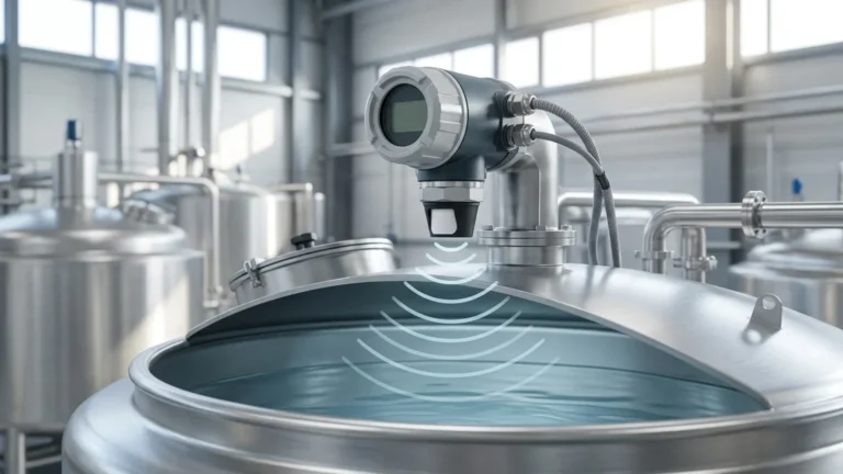
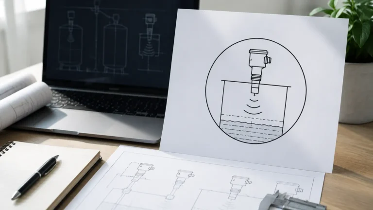
While flow meters measure horizontal velocity, Ultrasonic Level Meters measure vertical distance. The sensor emits an ultrasonic pulse toward the liquid surface. By measuring the time it takes for the echo to return, the device calculates the distance to the surface, which is then converted into a level or volume reading. In many 8-inch pipe applications, such as open-channel flow measurement, level and flow data are combined using flumes or weirs.
2. The Role of 8-Inch (DN200) Ultrasonic Flow Meters
The "8" in an 8 ultrasonic flow meter typically denotes an 8-inch nominal pipe diameter (DN200). This size is a standard in municipal water distribution, cooling water loops in power plants, and industrial wastewater discharge.
At this scale, non-invasive measurement becomes highly advantageous. Traditional mechanical meters for 8-inch pipes are heavy, expensive to install, and cause significant pressure drops. Clamp-on ultrasonic meters for DN200 pipes eliminate these issues by mounting to the exterior of the pipe, ensuring zero contact with the process fluid and no interruption to the flow during installation.
3. Technical Selection Criteria for 8-Inch Systems
Selecting the correct meter requires an analysis of the fluid properties and the physical environment. For an 8-inch application, the following parameters are essential:
| Feature | Specification for 8" (DN200) Pipe | Engineering Consideration |
| :— | :— | :— |
| Flow Range | 0.5 m/s to 12 m/s (1.6 to 39 ft/s) | Ensure the meter covers both peak and low-flow scenarios. |
| Accuracy | ±0.5% to ±2.0% of rate | Transit-time offers higher accuracy for clean liquids. |
| Pipe Material | Carbon Steel, Stainless Steel, PVC, Ductile Iron | Acoustic conductivity of the pipe wall affects signal strength. |
| Fluid Type | Potable water, chemicals, wastewater | Solids content determines if Transit-time or Doppler is required. |
| Output | 4-20mA, Modbus RTU, Pulse | Compatibility with existing PLC/SCADA systems. |
4. Installation Considerations for 8-Inch Pipelines
For an 8 ultrasonic flow meter to provide reliable data, the installation must account for the flow profile. Turbulence caused by valves, elbows, or pumps can lead to inaccurate readings.
Straight Pipe Requirements
The standard industry recommendation is the "10D Upstream / 5D Downstream" rule. For an 8-inch pipe, this means there should be at least 80 inches (approx. 2032 mm) of straight pipe before the meter and 40 inches (approx. 1016 mm) after it. If the installation is following a pump or a partially open valve, the upstream requirement may increase to 20D or 30D.
Transducer Mounting Methods
For DN200 pipes, two primary mounting configurations are used:
1. V-Method: The signal bounces off the opposite pipe wall once. This is the standard for 8-inch pipes as it provides a longer path length, increasing the time resolution and accuracy.
2. Z-Method: The transducers are placed on opposite sides of the pipe. This is used if the fluid is slightly attenuating or if the pipe wall is thick, as the signal only crosses the pipe once.
Coupling and Surface Preparation
Since air is a poor conductor of ultrasound, a coupling agent (grease or gel) must be used between the transducer and the pipe. For 8-inch pipes, the surface must be ground smooth to remove rust or scale to ensure a clear acoustic path.
5. Integration with Ultrasonic Level Meters
In many industrial scenarios, flow measurement in a pipe is only one part of the equation. For example, in a chemical dosing station, an 8 ultrasonic flow meter tracks the rate of chemical delivery, while Ultrasonic Level Meters monitor the inventory in the supply tanks.
This integration allows for:
* Mass Balance Calculations: Comparing the volume leaving the tank (via level change) with the volume measured by the flow meter to detect leaks.
* Pump Protection: Ensuring that pumps do not run dry by correlating flow rates with tank levels.
* Automated Refilling: Using level data to trigger supply valves, while the flow meter verifies the refill rate.
For comprehensive system design, engineers often source both types of instruments from a single manufacturer like Welk to ensure communication protocol compatibility and consistent UI/UX across the control platform.

6. Limitations and Environmental Factors
While ultrasonic technology is versatile, certain factors can limit the performance of an 8-inch flow or level system:
* Aeration and Bubbles: If the fluid in an 8-inch pipe contains more than 2% air bubbles by volume, the ultrasonic signal may be scattered, leading to a "signal loss" error.
* Pipe Liners: Thick cement or rubber liners in older 8-inch pipes can absorb the ultrasonic energy. In such cases, wetted (inline) transducers may be necessary instead of clamp-on versions.
* Temperature Extremes: High temperatures can change the speed of sound in the fluid. Advanced meters include temperature compensation to adjust the flow calculation automatically.
* Acoustic Short-Circuiting: In some metal pipes, the sound may travel through the pipe wall faster than through the fluid. Proper transducer spacing and frequency selection are required to filter out this noise.
7. Maintenance and Troubleshooting
One of the primary benefits of ultrasonic technology is the low maintenance requirement. Since there are no moving parts to wear out, the primary maintenance tasks involve:
1. Coupling Inspection: Periodically checking that the coupling gel has not dried out, especially in high-vibration environments.
2. Signal Strength Monitoring: Most modern meters provide a "Signal Quality" or "S/N Ratio" metric. A drop in this value usually indicates pipe scaling or grease buildup on the inner pipe wall.
3. Zero-Flow Calibration: Periodically checking the meter's reading under a no-flow condition to ensure there is no electronic drift.
8. Frequently Asked Questions (FAQ)
Q: Can an 8 ultrasonic flow meter measure steam or gas?
A: Standard transit-time meters are designed for liquids. While specialized ultrasonic gas flow meters exist, they operate at different frequencies and often require higher pressures to maintain signal integrity.
Q: How does pipe wall thickness affect the measurement?
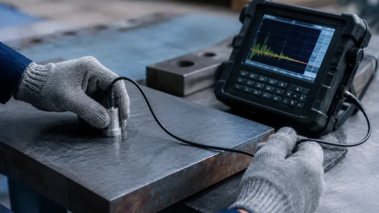
A: The meter must know the exact wall thickness to calculate the internal diameter and the refraction angle of the sound wave. For 8-inch pipes, using an ultrasonic thickness gauge before installation is highly recommended.
Q: Is it possible to use a portable 8-inch flow meter for temporary audits?
A: Yes, portable clamp-on ultrasonic meters are ideal for verifying the accuracy of existing mechanical meters in 8-inch lines without cutting the pipe.
Q: What is the difference between a single-path and multi-path meter?
A: A single-path meter uses one pair of transducers. A multi-path (e.g., 4-path or 8-path) meter uses multiple pairs to sample the flow velocity at different points in the pipe cross-section, providing much higher accuracy, especially where the flow profile is not fully developed.
Conclusion
The implementation of an 8 ultrasonic flow meter offers a non-invasive, cost-effective, and highly accurate solution for managing fluid dynamics in large-diameter piping. By understanding the acoustic principles and following strict installation guidelines regarding straight pipe runs and transducer mounting, process engineers can achieve reliable data for critical operations. When paired with Ultrasonic Level Meters, these tools form the backbone of modern industrial fluid management, ensuring both flow efficiency and inventory precision.
For those looking to upgrade their measurement infrastructure, selecting a manufacturer that offers customized OEM/ODM services ensures that the instrument is tailored to the specific acoustic properties of your process environment.