Ultrasonic Level Sensor Symbol
Understanding Ultrasonic Level Meters and the Ultrasonic Level Sensor Symbol in Industrial Engineering
In the field of industrial process automation, accurate level measurement is fundamental to operational safety, inventory management, and efficiency. Among the various technologies available, Ultrasonic Level Meters have emerged as a preferred solution for non-contact measurement in water treatment, chemical processing, and general manufacturing. For engineers and system designers, understanding both the physical application of these devices and their representation in technical documentation—specifically the ultrasonic level sensor symbol—is essential for successful project execution.
This guide explores the underlying principles of ultrasonic measurement, the standardized symbols used in Process and Instrumentation Diagrams (P&ID), and practical considerations for selecting and installing these instruments.
Measurement Principles of Ultrasonic Level Meters
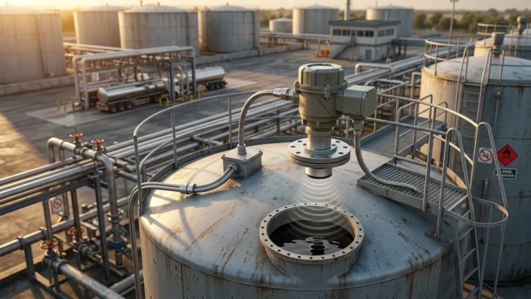
Ultrasonic level measurement is based on the "Time-of-Flight" (ToF) principle. The instrument consists of a transducer that functions as both a transmitter and a receiver.
The Time-of-Flight Process
1. Emission: The transducer emits a high-frequency ultrasonic pulse (typically between 20 kHz and 80 kHz) toward the surface of the medium.
2. Reflection: The sound wave travels through the air space in the tank, hits the surface of the liquid or solid material, and reflects back toward the sensor.
3. Reception: The transducer detects the returning echo.
4. Calculation: The internal electronics measure the time interval (t) between emission and reception. Since the speed of sound in air (c) is known, the distance (D) to the surface is calculated using the formula:
D = (c × t) / 2
The actual level (L) in the tank is then determined by subtracting the measured distance from the total tank height (H): L = H – D.
Temperature Compensation
The speed of sound is not constant; it varies with the temperature of the medium through which it travels (primarily air or gas). To maintain high accuracy, modern Ultrasonic Level Meters incorporate an integrated temperature sensor. This allows the device to automatically compensate for temperature fluctuations, ensuring that the distance calculation remains precise even as the ambient or process temperature changes.
The Ultrasonic Level Sensor Symbol in Engineering Documentation
In industrial engineering, technical drawings such as P&IDs serve as the blueprint for the entire system. To ensure clarity across different teams—from design to maintenance—standardized symbols are used to represent instruments. The ultrasonic level sensor symbol follows the standards set by the International Society of Automation (ISA), specifically ISA-5.1.
Component Identification
A standard instrument symbol consists of a "bubble" (a circle) containing a letter code that identifies the instrument's function. For an ultrasonic level transmitter, the code is typically LT (Level Transmitter) or LIT (Level Indicating Transmitter).
* L: First letter, indicating the measured variable (Level).
* I: Succeeding letter, indicating a readout or display (Indicator).
* T: Succeeding letter, indicating the transmission of the signal to a control system (Transmitter).
Graphic Representation
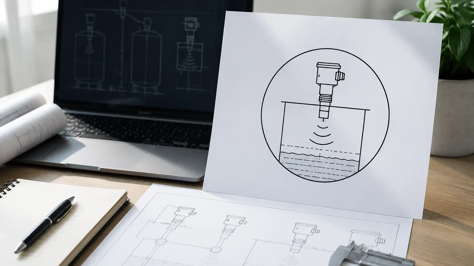
While the bubble identifies the function, the specific technology (ultrasonic) is often indicated by a graphic symbol or a note adjacent to the bubble. In many modern CAD libraries, the ultrasonic level sensor symbol includes a small icon representing the transducer head with radiating waves directed toward the process vessel.
* Line Types: A solid line connecting the symbol to the process vessel indicates a direct physical connection or mounting.
* Signal Lines: A dashed line or a line with cross-hatches indicates an electrical signal (e.g., 4-20mA or RS485) traveling from the sensor to a PLC or DCS.
Correctly identifying the ultrasonic level sensor symbol on a diagram ensures that technicians understand the non-contact nature of the measurement and the specific mounting requirements during the installation phase.
Selection Criteria for Industrial Applications
Choosing the right level meter requires a detailed analysis of the process environment. While ultrasonic technology is versatile, certain factors influence the performance and reliability of the device.
1. Measurement Range
Ultrasonic sensors have a maximum range determined by the power of the transducer. Standard industrial models often cover ranges from 5 meters (approx. 16.4 ft) up to 15 or 20 meters (approx. 65.6 ft). It is important to select a meter where the expected maximum distance falls comfortably within the sensor's effective range.
2. The "Dead Zone" (Blocking Distance)
Every ultrasonic sensor has a "dead zone" or "blocking distance" directly beneath the transducer face. In this zone (typically 0.2m to 0.5m), the sensor cannot accurately process the returning echo because the transducer is still vibrating from the emission. The sensor must be mounted high enough so that the maximum liquid level never enters this dead zone.
3. Material Compatibility
The housing and transducer face materials must be compatible with the process medium. For water and wastewater, standard plastic housings (like ABS or PVC) are often sufficient. For corrosive chemical applications, transducers made from PVDF (Polyvinylidene Fluoride) or PTFE (Teflon) are required to prevent degradation.
4. Output and Communication
Most industrial level meters provide a standard 4-20mA analog output. However, for integration into modern automation architectures, digital protocols such as Modbus RTU (RS485), HART, or Profibus are frequently specified to allow for remote configuration and advanced diagnostics.
Practical Selection Table
| Feature | Standard Application (Water/Oil) | Corrosive Application (Acids/Bases) | Long-Range Application (Silos/Deep Wells) |
| :— | :— | :— | :— |
| Transducer Material | ABS / Nylon | PVDF / PTFE | Reinforced Composite |
| Range | 0.4m – 10m | 0.25m – 8m | 0.5m – 20m+ |
| Accuracy | ±0.25% to ±0.5% | ±0.25% | ±0.5% |
| Output | 4-20mA | 4-20mA + HART | 4-20mA / RS485 |
| Protection Rating | IP65 / IP66 | IP67 / IP68 | IP66 / IP67 |
Installation Considerations and Best Practices
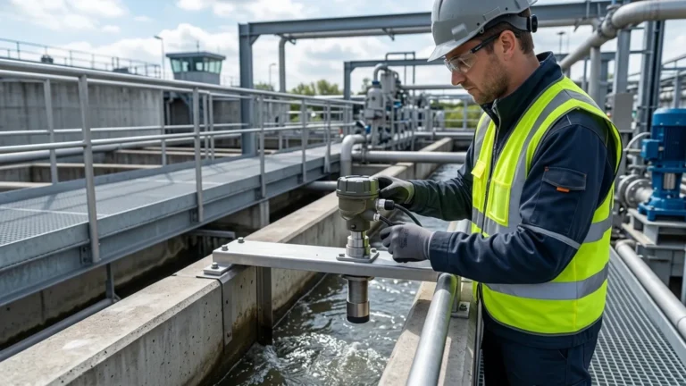
Proper installation is the most critical factor in the performance of Ultrasonic Level Meters. Since the technology relies on sound waves, any physical obstruction or environmental interference can cause false readings.
Positioning and Alignment
* Perpendicularity: The transducer face must be installed perfectly parallel to the liquid surface. If the sensor is tilted, the ultrasonic pulse will reflect away from the transducer rather than back to it, resulting in a "Loss of Echo" error.
* Avoid the Wall: Do not mount the sensor too close to the tank wall. Sound waves spread out in a cone shape (the beam angle, usually 5° to 12°). If the cone hits the tank wall, it will create parasitic echoes. A general rule is to maintain a distance from the wall equal to at least 1/6 of the tank height.
* Obstructions: Avoid mounting the sensor directly above internal tank structures such as ladders, agitators, or heating coils. If obstructions are unavoidable, many modern meters offer "false echo suppression" software to ignore these static reflections.
Environmental Factors
* Inflow: Do not mount the sensor directly above the tank's filling inlet. The turbulence and falling liquid will disrupt the ultrasonic signal.
* Vapor and Steam: While ultrasonic meters work well in many environments, heavy steam or dense vapors can attenuate the sound signal, reducing the effective range and accuracy.
* Pressure: Ultrasonic meters are typically designed for atmospheric or near-atmospheric pressure. High pressure changes the density of the air, significantly affecting the speed of sound and measurement reliability.
Limitations of Ultrasonic Technology
While highly effective, ultrasonic measurement is not a universal solution. Engineers should be aware of the following limitations:
1. Vacuum: Sound waves require a medium (air/gas) to travel. Therefore, ultrasonic meters cannot function in a vacuum.
2. Heavy Foam: Thick, dense foam on the surface of a liquid acts as an acoustic absorber. It soaks up the ultrasonic pulse rather than reflecting it, which can lead to measurement failure. In these cases, radar or hydrostatic transmitters are often preferred.
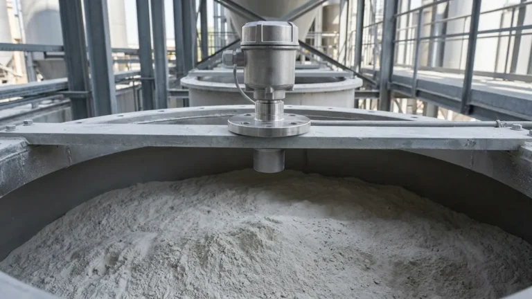
3. Extreme Dust: In solid level measurement (e.g., flour or fine powder), excessive dust in the air can scatter the sound waves. High-power transducers or radar technology are better suited for these conditions.
Frequently Asked Questions (FAQ)
Q: How does the ultrasonic level sensor symbol differ from a radar level sensor symbol?
A: In many P&ID standards, both may use the "LT" bubble. However, the graphic icon for radar often shows a horn antenna or a parabolic shape, whereas the ultrasonic symbol typically shows a flat transducer face with wavy lines representing sound pulses.
Q: What is the typical beam angle for these meters?
A: Most industrial ultrasonic transducers have a beam angle between 6° and 12°. A narrower beam angle is generally better for tall, narrow tanks as it helps avoid wall reflections.
Q: Can ultrasonic level meters be used for solids?
A: Yes, but with caution. Solids often have an uneven surface (angle of repose), which can reflect sound waves away from the sensor. For solids, it is recommended to use a meter with a higher power output and a swiveling mounting bracket to align the sensor with the material's surface.
Q: What maintenance is required?
A: Because they are non-contact, maintenance is minimal. However, the transducer face should be checked periodically for condensation or material buildup, especially in sticky or high-humidity applications. Many Welk sensors feature self-cleaning properties due to the vibration of the transducer, but manual inspection is still a best practice.
Conclusion
Ultrasonic Level Meters provide a reliable, cost-effective, and low-maintenance solution for a wide range of industrial level measurement tasks. By understanding the core principles of Time-of-Flight measurement and adhering to standardized documentation like the ultrasonic level sensor symbol, engineers can design systems that are both technically sound and easy to maintain.
When selecting an instrument, always prioritize the specific needs of the process—considering the range, chemical compatibility, and potential environmental interferences. For those seeking high-quality instrumentation, exploring professional Ultrasonic Level Meters ensures access to the latest advancements in signal processing and transducer technology, providing accurate data for critical process control decisions.