Level 4 Switches
Level 4 Switches
In industrial process control, the term "level 4 switches" typically refers to multi-point level detection systems designed to monitor four distinct stages within a vessel or tank. These stages are generally categorized as Low-Low (LL), Low (L), High (H), and High-High (HH). Implementing a robust 4-point switching strategy is essential for automated pump control, overflow prevention, and dry-run protection in sectors ranging from wastewater treatment to chemical processing.
Reliable level detection is the backbone of plant safety. Whether managing a simple water cistern or a pressurized chemical reactor, understanding the underlying physics of Level Switches allows engineers to select the most durable and accurate technology for their specific environment.
Understanding Measurement Principles for Level Switches
Before selecting a level 4 switches configuration, it is vital to understand how different sensing technologies interact with the process media. Each principle has distinct advantages depending on the physical properties of the liquid or solid being measured.
Vibrating Tuning Fork Principle
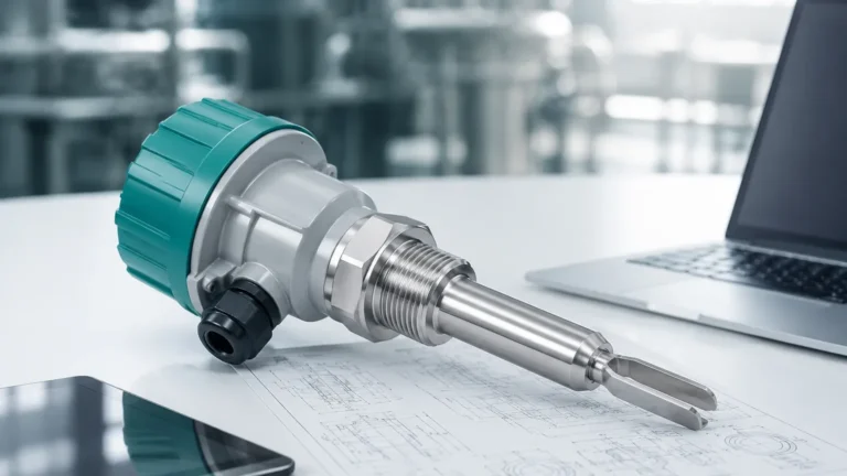
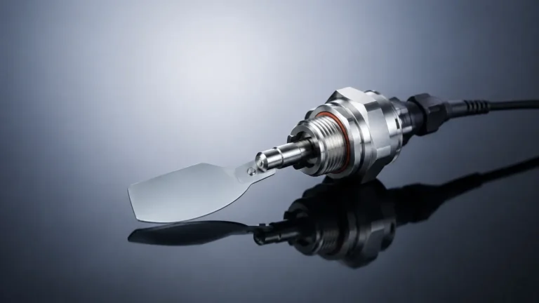
A vibrating level switch utilizes a tuning fork-shaped sensing element piezoelectrically energized to vibrate at its natural resonance frequency in the air. When the media reaches the fork, the frequency drops significantly due to the increased density of the surrounding material. This frequency shift is detected by the internal electronics and converted into a switching signal. This method is highly resistant to foam, bubbles, and external vibrations.
Float and Magnetic Principle
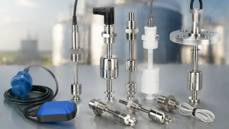
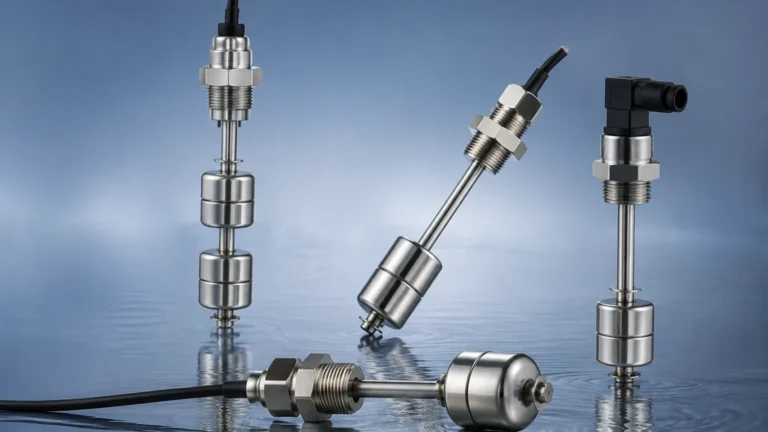
Magnetic float switches operate on the principle of buoyancy. A float containing a permanent magnet moves up and down a stem in response to the liquid level. Inside the stem, hermetically sealed reed switches are positioned at specific heights. As the magnet passes these points, the reed switches open or close. For 4-point detection, four separate reed switches are placed at the LL, L, H, and HH positions within a single probe assembly.
Capacitance Principle
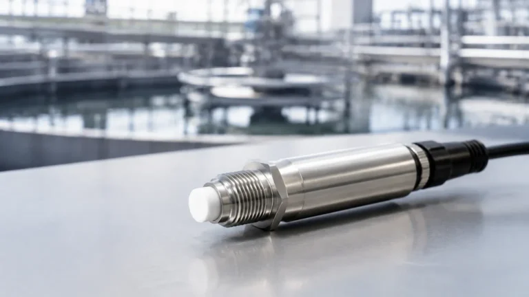
Capacitance switches measure the change in electrical capacitance between the sensing electrode and the tank wall (or a reference electrode). As the media covers the probe, the dielectric constant changes, altering the capacitance. This technology is excellent for detecting levels in powders or granulates, though it requires calibration based on the specific dielectric constant of the material.
Ultrasonic Point Detection
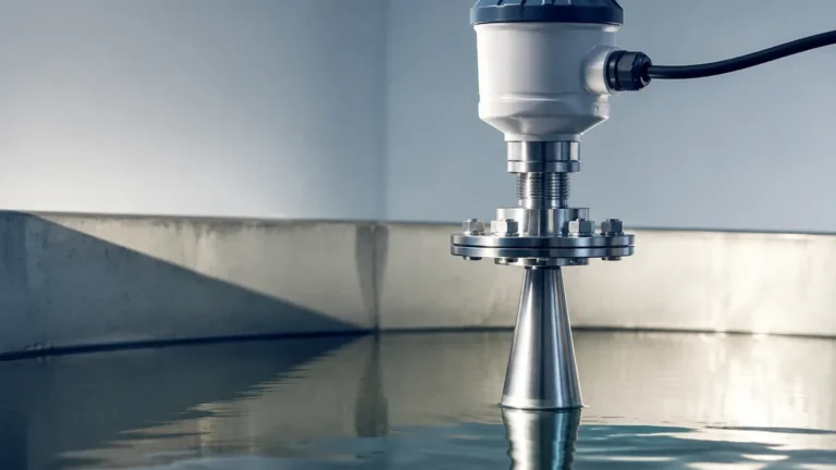
Ultrasonic switches use high-frequency sound waves. A transducer emits a pulse that travels through a gap in the sensor head. When the gap is filled with liquid, the pulse is transmitted; when empty, the pulse is attenuated. For level 4 switches applications, multiple ultrasonic sensors or a single integrated multi-point probe can be used to provide non-contact or gap-sensitive switching.
Types of Multi-Point Level 4 Switches
Achieving four points of detection can be done through a single integrated device or a combination of individual sensors. The choice depends on the tank geometry and the required redundancy.
1. Integrated Multi-Point Float Switches: These are the most common "level 4 switches" in water and oil applications. A single stainless steel or plastic stem contains four reed switches. This reduces the number of tank penetrations to one, simplifying installation.
2. Conductivity Probes: Used for conductive liquids, these probes use four electrodes of varying lengths. When the liquid touches an electrode, a circuit is completed back to the controller. This is a cost-effective solution for water-based applications but cannot be used with oils or non-conductive chemicals.
3. Arrayed Tuning Forks: In critical safety applications, four independent vibrating forks are installed at different heights. This provides the highest level of reliability and prevents a single point of failure from compromising the entire level control system.
4. Optical Level Switches: These use infrared light and a prism. When liquid covers the prism, the light is refracted into the liquid rather than reflected back to the sensor. While compact, they are typically used for single points, requiring four separate units for a level 4 setup.
Selection Criteria for Industrial Level Switches
Selecting the right Level Switches requires a deep dive into the process conditions. Engineers must evaluate the following parameters to ensure long-term stability.
Media Characteristics
* Viscosity: High-viscosity liquids can cause "clinging" on float switches or tuning forks, leading to false positives. Capacitance or non-contact ultrasonic switches are often preferred for thick syrups or sludges.
* Corrosiveness: For aggressive acids or bases, PTFE, PVDF, or high-grade Hastelloy coatings are necessary. Welk provides customized material options to ensure compatibility with volatile chemical environments.
* Conductivity: If using conductivity probes, the liquid must have a minimum conductivity (usually >10 μS/cm).
Process Conditions
* Temperature: Standard switches operate up to 80°C (176°F), but high-temperature variants can withstand up to 250°C (482°F) using ceramic seals and cooling fins.
* Pressure: In pressurized vessels, the float or sensor housing must be rated for the maximum possible pressure. Magnetic float switches often have pressure limits based on the float's collapse pressure (e.g., 30 bar / 435 psi).
Safety and Redundancy
In many level 4 switches configurations, the HH (High-High) and LL (Low-Low) points are designated as safety-critical alarms. These may require SIL (Safety Integrity Level) certification to ensure they function even if the primary control system fails.
Technical Comparison and Selection Table
| Technology | Media Type | Max Temp | Max Pressure | Maintenance Level | Best For |
| :— | :— | :— | :— | :— | :— |
| Tuning Fork | Liquids/Solids | 150°C | 40 bar | Low | Foam, bubbles, and turbulence |
| Magnetic Float | Clean Liquids | 200°C | 30 bar | Medium | Multi-point (4-point) detection |
| Capacitance | Solids/Liquids | 250°C | 100 bar | Medium | High pressure and powders |
| Conductivity | Conductive Liq. | 100°C | 10 bar | High | Low-cost water tanks |
| Ultrasonic | Clean Liquids | 80°C | 5 bar | Low | Non-contact requirements |

Installation Considerations for 4-Point Level Detection
Proper installation is as important as sensor selection. Even the most advanced level 4 switches will fail if positioned incorrectly.
1. Avoiding Turbulence
If the tank has an agitator or a high-velocity inlet, the resulting turbulence can cause floats to bounce or tuning forks to chatter. In these cases, a stilling well (a pipe surrounding the sensor) should be installed to provide a calm surface for measurement.
2. Mounting Position
Switches should be mounted away from the fill stream to prevent the force of the incoming liquid from triggering the sensor prematurely. For multi-point float switches, ensure there is enough vertical clearance to remove the entire stem for maintenance.
3. Wiring and Signal Integration
Level 4 switches generate four separate digital signals. These should be wired into a PLC (Programmable Logic Controller) or a dedicated level controller. It is recommended to use normally closed (NC) circuits for high-level alarms; this ensures that if a wire breaks, the system fails into an alarm state (fail-safe).
4. Dead Zones and Switching Differential
Every switch has a "dead zone" or hysteresis—the distance between the point where the switch activates and where it deactivates. When setting the four points, ensure there is sufficient distance between them (typically at least 50mm or 2 inches) to prevent overlapping signals and rapid cycling of pumps.
Limitations and Common Risks
While level switches are reliable, they are not without limitations. Engineers should be aware of the following risks:
* Build-up and Coating: In wastewater or mining slurries, material can build up on the sensor. Vibrating forks are better at shedding build-up than static probes, but periodic cleaning is still required.
* Mechanical Wear: Float switches have moving parts. Over millions of cycles, the pivot points or the reed switches themselves can wear out. In high-cycle applications, solid-state sensors like tuning forks are superior.
* Specific Gravity Changes: Float switches rely on the liquid being denser than the float. If the process media changes (e.g., switching from water to a light oil), the float may no longer reach the switching point.
* False Triggers from Foam: Some sensors, like ultrasonic or capacitance, may struggle to distinguish between a thick layer of foam and the actual liquid level. Tuning forks are generally the most reliable in heavy foam conditions.
Frequently Asked Questions (FAQs)
Q: Can I use a single level 4 switch for both pump control and safety shutdown?
A: While technically possible with a 4-point switch, industrial safety standards often recommend using a separate, independent switch for the High-High (HH) safety shutdown to ensure redundancy in case the primary controller fails.
Q: What is the maximum length for a multi-point level 4 float switch?
A: Most manufacturers, including Welk, can produce stems up to 4 meters (approx. 13 feet). For deeper tanks, hydrostatic pressure transmitters or radar level meters are often more practical than long mechanical stems.
Q: How do I test my level 4 switches without filling the tank?
A: For float switches, you can manually lift the float if the tank is empty. For tuning forks, many models include a "test" magnet or button that simulates a frequency shift to verify the electronics and wiring.
Q: Are level 4 switches suitable for hygienic food and beverage applications?
A: Yes, but they must feature sanitary fittings (like Tri-Clamp) and be constructed from 316L stainless steel with a high surface finish (Ra < 0.8 μm) to prevent bacterial growth.
Conclusion
Implementing level 4 switches provides a comprehensive view of tank status, allowing for sophisticated automation and multi-layered safety protocols. By selecting the appropriate measurement principle—whether it be the versatility of a tuning fork or the multi-point efficiency of a magnetic float—operators can ensure high accuracy and minimal downtime. When designing your system, always account for media viscosity, potential build-up, and the need for fail-safe wiring. For specialized configurations or harsh environment compatibility, consulting with a manufacturer like Welk ensures that your level measurement solution is tailored to your specific industrial requirements.