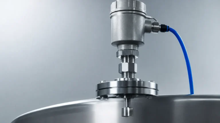
Switches Level
Switches Level
In industrial process control, point level detection serves as a fundamental safeguard for equipment and personnel. Unlike continuous level transmitters that provide a constant stream of data regarding the volume or height of a substance, level switches are designed to detect the presence or absence of a material at a specific, predetermined point. Often referred to in engineering contexts as switches level devices, these instruments are primarily utilized for high-level alarms (overfill protection), low-level alarms (run-dry prevention), and pump control logic.
Selecting the appropriate technology for level switches requires a deep understanding of the physical properties of the media, the environmental conditions of the vessel, and the specific requirements of the control system. This guide provides a technical overview of common measurement principles, selection criteria, and installation best practices for industrial applications.
Measurement Principles of Level Switches
To ensure reliable performance, engineers must match the physical sensing principle of the switch to the characteristics of the liquid or solid being measured. The following are the most common principles utilized in modern industrial instrumentation.
Float Level Switches
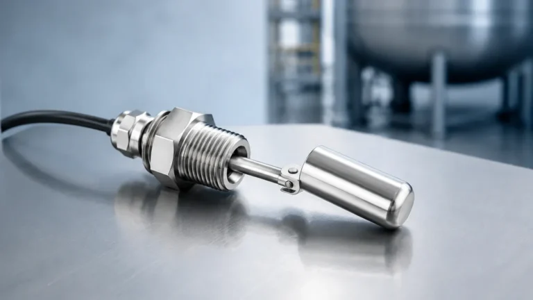
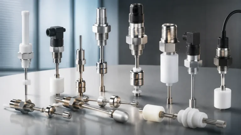
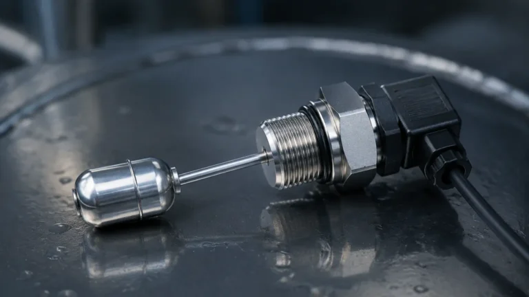
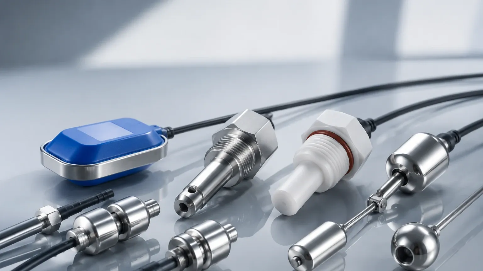
Float switches operate on the principle of buoyancy. A float containing a permanent magnet moves with the surface of the liquid. When the float reaches a specific point, the magnetic field actuates a hermetically sealed reed switch located within the stationary stem. These are among the most cost-effective solutions for clean liquids. However, they are susceptible to mechanical failure if the media contains debris or high viscosity that causes the float to stick.
Vibrating Fork (Tuning Fork) Switches
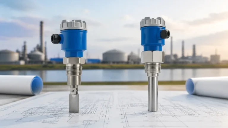
The sensing element of a vibrating fork switch consists of two tines that are vibrated at their resonant frequency by a piezoelectric crystal. When the tines are immersed in a liquid or solid, the frequency of vibration changes or the amplitude is dampened. The internal electronics detect this shift and trigger the output. These Level Switches are highly versatile, as they are largely unaffected by flow, turbulence, bubbles, or foam.
Capacitance Level Switches
Capacitive sensors treat the probe and the vessel wall (or a reference electrode) as two plates of a capacitor. The material being measured acts as the dielectric. As the level rises and covers the probe, the capacitance increases because the dielectric constant of the material is higher than that of air. This change is converted into a switching signal. This technology is excellent for both liquids and solids but requires calibration based on the specific dielectric constant of the media.
Conductive Level Switches
Conductive switches are used exclusively with conductive liquids. A low-voltage, low-current circuit is established between two electrodes (or one electrode and a metal tank wall). When the liquid touches the electrodes, the circuit is completed. These are simple and reliable for water-based applications but cannot be used with oils, hydrocarbons, or pure distilled water.
Ultrasonic Point Level Switches
Ultrasonic switches utilize a pair of crystals (transmitter and receiver) separated by a small gap. When the gap is filled with air, the ultrasonic signal is attenuated. When liquid fills the gap, the signal is transmitted efficiently to the receiver, triggering the switch. These are non-contact in terms of moving parts and are ideal for corrosive or highly viscous fluids where mechanical floats would fail.
Selection Criteria for Industrial Applications
Choosing the right switches level configuration involves evaluating several technical parameters to prevent premature failure or false triggering. The following factors are critical:
1. Media State and Density: Is the material a liquid, a slurry, or a granular solid? For solids, the bulk density (measured in kg/m³ or lb/ft³) determines if a vibrating probe or rotating paddle is more appropriate. For liquids, density affects the buoyancy of float-style switches.
2. Process Temperature and Pressure: Standard switches may operate up to 80°C (176°F), but high-temperature variants utilizing ceramic seals or cooling fins can handle upwards of 250°C (482°F). Pressure ratings must exceed the maximum potential surge pressure of the vessel, often reaching 40 bar (580 psi) or higher in specialized applications.
3. Chemical Compatibility: The wetted parts—the components in direct contact with the media—must be resistant to corrosion. Common materials include 316L stainless steel, PTFE (Teflon), PP (Polypropylene), and PVDF.
4. Viscosity and Coating: Highly viscous fluids or materials that leave a film (coating) can cause false positives. Vibrating forks with "active shield" technology or specific capacitance probes are designed to ignore build-up.
5. Hazardous Area Requirements: If the environment contains explosive gases or dust, the switch must be rated as Intrinsically Safe (IS) or Explosion-Proof (Ex d) according to ATEX, IECEx, or local standards.
Technical Comparison Table
| Technology | Media Type | Max Temp (Approx) | Max Pressure (Approx) | Viscosity Tolerance | Coating Resistance |
| :— | :— | :— | :— | :— | :— |
| Float | Clean Liquids | 120°C | 30 bar | Low | Poor |
| Vibrating Fork | Liquids/Solids | 250°C | 64 bar | Moderate to High | High |
| Capacitance | Liquids/Solids | 200°C | 100 bar | Moderate | Moderate |
| Conductive | Conductive Liquids | 100°C | 10 bar | Moderate | Low |
| Ultrasonic | Liquids | 150°C | 40 bar | High | Moderate |
Installation Guidelines and Best Practices
Proper installation is as important as technology selection. Even the most advanced switches level instrument will fail if positioned incorrectly.
* Avoid the Inflow Stream: Never install a level switch directly in the path of the filling stream. The force of the material can cause mechanical damage or trigger false high-level alarms due to splashing.
* Orientation: Vibrating forks used in liquids are typically mounted horizontally, while those used in solids may be mounted vertically or at an angle to prevent material from bridging between the tines. If mounted horizontally, ensure the tines are oriented vertically (on edge) so that material can easily fall away.
* Nozzle Length: Ensure the sensing element extends sufficiently into the vessel. If the mounting nozzle is too long, material (especially solids or viscous liquids) can become trapped in the nozzle, causing the switch to remain in the "covered" state even when the vessel is empty.
* Dead Zones: Be aware of the "dead zone" or non-responsive area near the mounting threads or flange. The active sensing portion of the probe must be clear of the tank wall to avoid interference.
* Wiring and Sealing: Use appropriate cable glands to maintain the IP (Ingress Protection) rating of the housing. In outdoor installations, always include a drip loop in the wiring to prevent moisture from following the cable into the electronics enclosure.
Limitations and Environmental Considerations
While level switches are robust, they have specific limitations that engineers must account for during the design phase:
* Turbulence and Agitation: In tanks with mixers or high-velocity inflows, mechanical switches like floats can be damaged. In these cases, vibrating forks or non-contact ultrasonic switches are preferred. If a float must be used, a stilling well (a perforated pipe) should be installed to dampen the liquid movement.
* Foam: Most point level switches struggle with heavy foam. A capacitance switch might detect the foam as a liquid, while an ultrasonic switch might have its signal absorbed. If the goal is to detect the liquid level *under* the foam, specific tuning of a vibrating fork or a displacement-style switch may be required.
* Vacuum Conditions: Some switches, particularly those using certain seal materials, may not be rated for full vacuum. Always verify the absolute pressure range of the instrument.
* Electromagnetic Interference (EMI): In environments with large motors or variable frequency drives (VFDs), electronic switches (capacitance/ultrasonic) must be properly grounded and shielded to prevent signal noise from causing false trips.
Maintenance and Troubleshooting
Level switches are often "set and forget" devices, but they require periodic verification, especially when used in safety-critical overfill protection systems.
1. Proof Testing: Periodically raise the level of the media (or manually actuate the switch) to ensure the control loop responds correctly. This is a requirement for SIL (Safety Integrity Level) rated systems.
2. Cleaning: For applications involving wastewater or crystallization, inspect the probes for build-up. While many modern switches level designs are "self-cleaning" to an extent, heavy scaling will eventually impede performance.
3. Seal Inspection: Check for signs of moisture or corrosion inside the electronics housing, which indicates a failure of the conduit seals or the primary process seal.
Frequently Asked Questions (FAQ)
Q: Can a level switch be used for continuous level measurement?
A: No. A level switch only provides a binary output (on/off). For continuous tracking of level percentage or volume, a radar, ultrasonic, or hydrostatic level transmitter is required.
Q: What is the difference between NPN and PNP outputs in electronic level switches?
A: These refer to the type of transistor output used in DC circuits. PNP (source) switches provide a positive voltage when activated, while NPN (sink) switches connect the load to the negative/ground side. The choice depends on the input requirements of your PLC (Programmable Logic Controller).
Q: How do I handle a level switch in a tank that contains a thick layer of foam?
A: If you want to ignore the foam and only detect the liquid, a vibrating fork switch with adjusted sensitivity or a conductive switch (if the liquid is conductive) is often the best choice. Capacitance switches can also be tuned to ignore the low dielectric constant of foam.
Q: Is it possible to use a single switch for both high and low-level control?
A: A single point level switch can only detect one level. However, some specialized probes have two or more sensing points on a single stem, or you can use a controller that logic-latches two separate switches to start and stop a pump.
By understanding these principles and constraints, engineers can ensure that their switches level selections provide reliable, long-term service in even the most demanding industrial environments.