Switch Level 2 vs 3
Switch Level 2 vs 3
In the landscape of industrial automation and process control, the terminology surrounding "levels" can often lead to confusion. When engineers discuss a switch level 2 vs 3, they are typically referring to one of two critical frameworks: the ISA-95 functional hierarchy of industrial control systems or the Safety Integrity Level (SIL) ratings defined by IEC 61508/61511. For a professional manufacturer like Welk, understanding these distinctions is vital for integrating Level Switches into sophisticated plant architectures.
This article examines the technical nuances of level switch integration across different automation layers and safety requirements, providing a practical guide for selection, installation, and system design.
Understanding Level Switch Measurement Principles
Before determining the integration level (Level 2 or Level 3), it is essential to understand the physical measurement principles of the hardware. Level switches are point-level detection devices that trigger a discrete output when a substance reaches a specific height in a vessel.
1. Vibrating Tuning Fork Switches
These switches utilize a piezoelectric crystal to vibrate a metal fork at its natural frequency. When the fork is immersed in a liquid or solid, the frequency changes or the vibration is dampened. The internal electronics detect this shift and switch the output state. They are highly resistant to turbulence and bubbles.
2. Float Level Switches
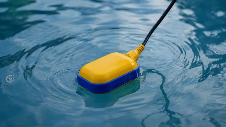
Operating on the principle of buoyancy, a magnetic float moves with the liquid level along a stem. When the float reaches a reed switch embedded in the stem, the magnetic field closes or opens the circuit. These are cost-effective but limited to clean, non-coating liquids.
3. Capacitance Level Switches
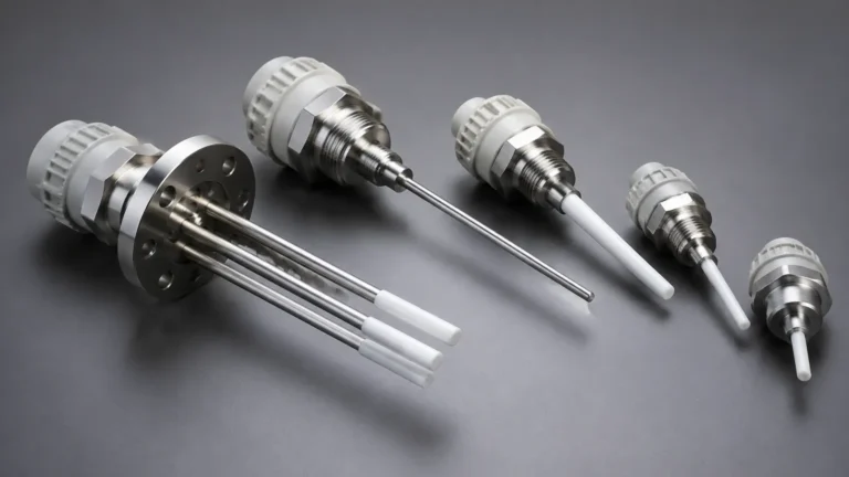
These sensors measure the change in electrical capacitance between the probe and the tank wall (or a reference electrode). As the process material displaces air, the dielectric constant changes, altering the capacitance. These are ideal for powders, granules, and corrosive liquids.
4. Ultrasonic Level Switches
Ultrasonic switches use a pair of transducers to send and receive high-frequency sound waves across a gap. When liquid fills the gap, the sound waves are transmitted; when the gap is empty (filled with air/gas), the signal is attenuated. This non-contact-adjacent technology is excellent for highly viscous or sticky media.
Defining Switch Level 2 vs 3 in Industrial Automation
In the context of the ISA-95 model, the distinction between Level 2 and Level 3 relates to where the data from the level switch is processed and how it influences the enterprise.
Level 2: Supervisory Control (The PLC/SCADA Layer)
Level 2 is the domain of real-time process control. When a level switch is integrated at this level, its primary function is to provide immediate feedback to a Programmable Logic Controller (PLC) or a Distributed Control System (DCS).
* Function: Automatic pump control, high-level alarms, and dry-run protection.
* Communication: Typically hardwired (4-20mA, Relay, PNP/NPN) or connected via local fieldbus (Modbus RTU, PROFIBUS).
* Response Time: Milliseconds. The system must react instantly to prevent tank overflows or equipment damage.
Level 3: Operations Management (The MES Layer)
Level 3 involves Manufacturing Execution Systems (MES) and operations management. At this level, the data from the level switch is no longer just about a single pump; it is about inventory management, batch tracking, and production efficiency.
* Function: Calculating material usage rates, triggering supply chain orders, and analyzing long-term equipment reliability.
* Communication: Data is often bridged from Level 2 via Industrial Ethernet (PROFINET, EtherNet/IP) or MQTT for cloud-based monitoring.
* Response Time: Seconds to minutes. The focus is on data aggregation and historical analysis rather than immediate mechanical control.
Switch Level 2 vs 3 in Safety Systems (SIL)
Another frequent interpretation of "switch level 2 vs 3" refers to Safety Integrity Levels (SIL). This is a measure of the reliability and risk reduction provided by a Safety Instrumented Function (SIF).
| Feature | SIL 2 Level Switch | SIL 3 Level Switch |
| :— | :— | :— |
| Target Risk Reduction | 100 to 1,000 times | 1,000 to 10,000 times |
| Probability of Failure (PFDavg) | ≥ 10⁻³ to < 10⁻² | ≥ 10⁻⁴ to < 10⁻³ |
| Hardware Fault Tolerance (HFT) | Typically 0 (1oo1) with high diagnostic coverage | Typically 1 (1oo2 or 2oo3) |
| Application | Standard hazardous chemical storage | Critical high-pressure reactors, explosive environments |
| Maintenance | Annual proof testing common | Frequent, rigorous proof testing required |
Selecting a SIL 3 solution often requires redundant Level Switches configured in a voting logic (e.g., two-out-of-three) to ensure that a single component failure does not compromise the safety of the entire plant.
Technical Comparison: Integration and Performance
Choosing between a Level 2 focused setup and a Level 3 integrated system depends on the complexity of the facility.
Data Granularity
Level 2 switches provide binary data (On/Off). To move to Level 3, modern "smart" level switches are used. These devices utilize IO-Link or HART protocols to provide secondary data, such as internal temperature, electronics health, and the number of switching cycles. This "Level 3 data" allows for predictive maintenance, where a switch is replaced before it fails based on its actual usage profile.
Network Infrastructure
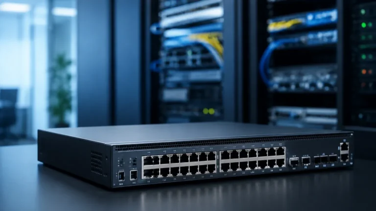
For Level 2, simple twisted-pair wiring is sufficient. For Level 3 integration, the facility requires a robust Industrial Ethernet backbone. This is where the term "Layer 2 vs Layer 3" from networking often intersects with industrial instrumentation. Layer 2 network switches handle data within a single VLAN (local control loop), while Layer 3 network switches route data between different subnets (from the factory floor to the corporate office).
Practical Selection Table for Level Switches
| Media Type | Recommended Switch Technology | Primary Integration Level | Typical Output |
| :— | :— | :— | :— |
| Water / Wastewater | Float or Ultrasonic | Level 2 (Pump Control) | Relay / 4-20mA |
| Corrosive Chemicals | Capacitance (PTFE coated) | Level 2 & 3 (Safety & Inventory) | HART / IO-Link |
| Viscous Oils | Tuning Fork (High Sensitivity) | Level 2 (Overfill Prevention) | PNP / NPN |
| Granular Solids | Rotating Paddle or Capacitance | Level 3 (Inventory Management) | Modbus / Ethernet |
| High-Pressure Steam | Magnetic Level Gauge Switch | Level 2 (Boiler Safety) | Dry Contact |

Installation Considerations and Limitations
To ensure a level switch performs reliably at any integration level, specific installation guidelines must be followed:
1. Avoid Turbulence: Do not install switches directly in the path of the filling stream. This can cause "chatter" or false triggering. If necessary, use a stilling well.
2. Mounting Position: Horizontal mounting is common for side-entry switches, but ensure the cable gland points downward to prevent moisture ingress (the "drip loop" principle).
3. No-Go Zones: For ultrasonic switches, ensure there are no internal obstructions (ladders, agitators) within the signal beam's path. The beam angle is typically 5° to 10°.
4. Dead Zones: Every switch has a physical limit. For ultrasonic types, there is a "blocking distance" (typically 0.2m to 0.5m) where measurements are impossible. For tuning forks, the "dead zone" is the length of the fork itself (usually 40mm to 100mm).
5. Grounding: Ensure the instrument is properly grounded to the vessel, especially in capacitance applications, to prevent EMI (Electromagnetic Interference) from distorting the signal.
Limitations
* Coating and Buildup: While tuning forks can handle some coating, heavy sludge or crystallizing liquids can bridge the forks, causing a permanent "high" signal.
* Dielectric Constant: Capacitance switches require a minimum dielectric constant (εr) to function. If the media changes (e.g., switching from oil to water), the switch may require recalibration.
* Pressure and Temperature: Always verify that the process conditions do not exceed the switch's rating. Standard switches operate up to 2 MPa (20 bar) and 150°C; specialized high-pressure models are required for more extreme environments.
Maintenance and Troubleshooting
Reliability in a Level 3 system depends on the quality of the data coming from Level 1 (the sensor).
* Proof Testing: For safety-critical switches, periodic proof testing is mandatory. This involves manually raising the liquid level or using a test button to verify the entire loop (Sensor -> PLC -> Final Control Element).
* Cleaning: In wastewater or food processing, sensors should be inspected every 3–6 months for biological growth or material buildup.
* Diagnostic Alarms: Modern switches integrated into Level 3 systems can report "Internal Error" or "Supply Voltage Low." These should be mapped to the HMI to alert technicians before a total failure occurs.
Frequently Asked Questions (FAQs)
Q: Can a Level 2 switch be upgraded to Level 3?
A: Yes, by using a gateway or a remote I/O module that converts standard relay or 4-20mA signals into an industrial Ethernet protocol like EtherNet/IP or PROFINET. However, for full Level 3 benefits (like diagnostics), a native smart switch is preferred.
Q: Is SIL 3 always better than SIL 2 for level measurement?
A: Not necessarily. SIL 3 increases complexity and cost significantly. It should only be used where the Risk Assessment (HAZOP/LOPA) specifically requires that level of risk reduction. For most standard industrial applications, SIL 2 is the industry standard for safety.
Q: What is the maximum distance for a Level 2 switch signal?
A: For standard relay outputs, distances of up to 500 meters are possible with shielded cable. For IO-Link, the limit is strictly 20 meters. For longer distances in Level 3 architectures, fiber optic or Ethernet repeaters are required.
Q: How does viscosity affect the choice between Level 2 and Level 3 switches?
A: Viscosity affects the hardware choice (Principle), not the integration level. For high viscosity, a tuning fork or ultrasonic switch is better than a float. Once the signal is generated, it can be sent to either Level 2 or Level 3 systems regardless of the fluid's thickness.
Conclusion
Distinguishing between switch level 2 vs 3 requires a dual focus on the automation hierarchy and safety requirements. Level 2 integration ensures that your process remains under control in real-time, preventing immediate hazards and maintaining operational flow. Level 3 integration transforms your level switches from simple alarms into data points for enterprise-wide optimization and predictive maintenance.
Whether you are designing a simple pump control circuit or a complex, SIL-rated safety system, selecting the right technology from a trusted manufacturer like Welk ensures that your Level Switches provide the accuracy and reliability demanded by modern industrial standards. Always consult the specific process parameters—pressure, temperature, and media characteristics—before finalizing your system architecture.