Level 2 Switches
Level 2 Switches
In the landscape of industrial automation and process safety, the term "level 2 switches" typically refers to secondary point-level detection devices used for redundancy or high-level safety interlocks. While a primary sensor (Level 1) manages the daily operational range of a tank or vessel, the Level 2 switch acts as a critical safeguard, often configured as a "High-High" or "Low-Low" alarm to prevent catastrophic overfills or pump dry-running.
Reliable point-level detection is the cornerstone of risk management in sectors such as water treatment, chemical processing, and oil and gas. Selecting the correct technology for these secondary safety layers requires a deep understanding of measurement principles, media characteristics, and environmental constraints.
Measurement Principles for Point Level Detection
Before selecting Level Switches for a secondary safety layer, engineers must evaluate the physical principles that govern different sensor types. Each technology interacts with the process media differently, impacting its reliability as a Level 2 safety device.
Vibrating Fork (Tuning Fork) Technology
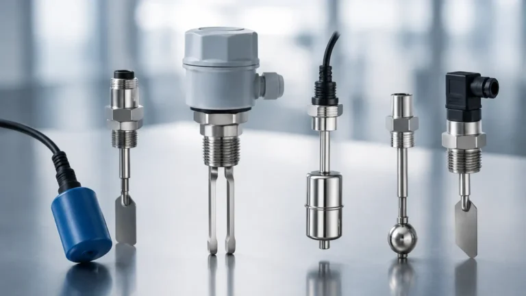
Vibrating fork switches utilize piezoelectric crystals to energize a metal fork at its natural resonant frequency (typically around 1,200 Hz). When the fork is immersed in a liquid or solid, the frequency shifts or the amplitude of the vibration is dampened. An internal electronic circuit detects this change and triggers a relay output. This method is highly resistant to changes in pressure, temperature, and foam, making it a preferred choice for overfill prevention.
Float and Magnetic Level Switches
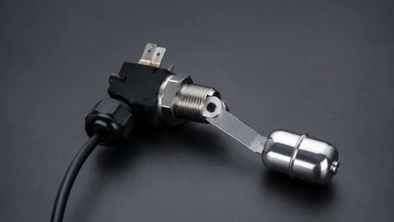
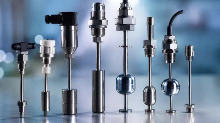
These switches operate on the principle of buoyancy. A float containing a permanent magnet moves along a guide tube as the liquid level rises or falls. Inside the tube, a hermetically sealed reed switch is actuated by the magnetic field. Because they are mechanically simple and do not require external power to operate the sensing element, they are frequently used in Level 2 applications where electrical simplicity is prioritized.
Capacitive Level Sensing
Capacitive switches treat the sensor probe and the vessel wall as two plates of a capacitor. The process media acts as the dielectric material. As the level rises and covers the probe, the capacitance increases based on the dielectric constant (ε) of the material. This technology is effective for detecting powders, granulates, and liquids, though it may require calibration to account for material build-up on the probe.
Ultrasonic Point Level Switches
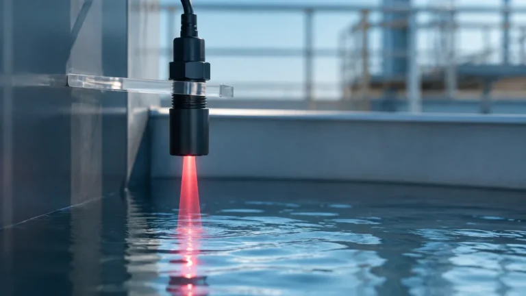
Ultrasonic switches use a pair of crystals (transmitter and receiver) separated by a small gap. When the gap is filled with liquid, ultrasonic waves travel across it; when the gap is empty (filled with air or gas), the signal is attenuated. This non-contact or gap-based sensing is ideal for clean liquids where mechanical movement must be avoided.
The Role of Level 2 Switches in Process Safety
In industrial engineering, a Level 2 switch is rarely the only instrument on a tank. Instead, it forms part of a layered protection strategy.
1. Redundancy: If a continuous radar or ultrasonic transmitter fails or provides an erroneous reading due to signal interference, the Level 2 switch provides an independent hardware-based confirmation that a specific limit has been reached.
2. Safety Instrumented Systems (SIS): Level 2 switches are often integrated into an SIS to achieve specific Safety Integrity Levels (SIL). In these configurations, the switch is wired directly to an emergency shutdown (ESD) valve or a power-cut relay for a pump, bypassing the primary PLC control logic.
3. Environmental Compliance: For hazardous chemicals, a Level 2 "High-High" switch is often a regulatory requirement to prevent spills that could lead to environmental contamination or fire hazards.
Key Evaluation Criteria for Industrial Applications
Selecting a Level 2 switch requires matching the sensor's physical limits to the process conditions. The following table provides a general comparison of common technologies used in industrial environments.
| Technology | Media Type | Max Temperature | Max Pressure | Best For |
| :— | :— | :— | :— | :— |
| Vibrating Fork | Liquids/Solids | -50°C to +150°C | Up to 64 bar | Overfill prevention, foam resistance |
| Magnetic Float | Clean Liquids | -20°C to +200°C | Up to 40 bar | Simple interlocks, no power required |
| Capacitive | Liquids/Solids | -40°C to +200°C | Up to 25 bar | Powders, non-conductive liquids |
| Conductivity | Conductive Liquids | Up to 100°C | Low pressure | Water/Acid detection, low cost |
Media Considerations
* Viscosity: High-viscosity liquids can cause "bridging" in vibrating forks or stickiness in float mechanisms.
* Dielectric Constant: For capacitive switches, the media must have a dielectric constant significantly different from air (ε > 1.5).
* Corrosivity: Level 2 switches in chemical tanks often require 316L Stainless Steel, PTFE coating, or Hastelloy components to withstand aggressive acids or bases.
Installation and Engineering Considerations
Proper installation is critical for ensuring that a Level 2 switch performs its safety function when called upon. Even the most advanced sensor will fail if positioned incorrectly.
Orientation and Positioning
* Horizontal vs. Vertical: Vibrating forks are typically installed horizontally through the side of the tank at the exact alarm point. Floats may be installed vertically from the top or horizontally depending on the design.
* Avoid the Fill Stream: Switches should never be installed directly under a fill pipe. The turbulence and splashing can cause false alarms or mechanical damage to the probe.
* Nozzle Length: For vibrating forks, the nozzle length must be short enough to ensure the forks fully extend into the vessel. If the forks remain inside a narrow nozzle, material may build up and cause a permanent "wet" signal.
Turbulence and Agitation
In tanks with agitators, the mechanical forces of moving liquid can bend or snap long probe switches. In these cases, a protective baffle or a stilling well should be installed to shield the Level 2 switch from lateral forces while still allowing the liquid level to reach the sensor.

Limitations and Common Risks
While Level 2 switches are designed for reliability, they are not immune to failure. Engineers must account for the following risks during the design phase:
* Material Build-up: In applications involving wastewater or slurries, material can coat the sensor. While vibrating forks have some self-cleaning properties due to their vibration, heavy scaling can eventually dampen the signal.
* Gas Pockets: In float-based systems, gas bubbles trapped in the guide tube can prevent the float from rising, leading to a failure to alarm during an overfill.
* Electronic Component Drift: Over time, the internal oscillators or capacitors in electronic switches can drift due to thermal cycling. Regular functional testing (proof testing) is required to ensure the switch still trips at the intended setpoint.
Maintenance and Functional Testing
Because Level 2 switches are often in a "de-energized" or "standby" state for long periods, they can suffer from dormant failures. A robust maintenance schedule should include:
1. Visual Inspection: Check for corrosion on the housing, integrity of the cable glands, and signs of leaking at the process connection.
2. Wet Testing: Whenever possible, the level should be raised during a controlled maintenance window to physically trip the switch. This confirms the entire loop—from the sensor to the alarm or pump relay—is functioning.
3. Simulation: For switches with internal diagnostics, a test button or magnetic test point can be used to simulate a high-level condition electronically. While useful, this does not replace a full wet test of the physical sensing element.
Frequently Asked Questions (FAQ)
Q: Can a continuous level transmitter be used as a Level 2 switch?
A: While a radar or ultrasonic transmitter can provide a high-level alarm via software, it is generally recommended to use a dedicated point-level switch for Level 2 protection. This provides hardware diversity, ensuring that a software glitch or signal loss in the primary transmitter does not disable the safety alarm.
Q: What is the difference between a normally open (NO) and normally closed (NC) configuration for a safety switch?
A: For safety applications, "normally closed" (fail-safe) is preferred. In this configuration, the circuit is closed during normal operation and opens when the alarm point is reached or if power is lost. This ensures that a broken wire is detected immediately as an alarm condition.
Q: How do I handle foam in a Level 2 overfill application?
A: Vibrating fork switches are generally the best choice for foam-prone environments, as they can be tuned to ignore light foam and only trigger when the liquid phase reaches the forks. Ultrasonic and capacitive sensors may struggle with dense foam, often triggering prematurely.
For technical specifications and to explore various industrial options, you may Review product options and application support to find a solution tailored to your specific process requirements.