Level 4 Switch
Level 4 Switch
In industrial process control, monitoring liquid levels at multiple points is essential for preventing overflows, protecting pumps from dry running, and maintaining optimal inventory. A level 4 switch refers to a multi-point level detection system designed to monitor four distinct levels within a single tank or vessel. These systems provide discrete signals to a Programmable Logic Controller (PLC) or Distributed Control System (DCS) to trigger specific actions, such as starting or stopping pumps and activating safety alarms.
By integrating four switching points into a single probe or mounting assembly, engineers can reduce the number of tank penetrations, simplify wiring, and lower overall installation costs. This guide explores the measurement principles, selection criteria, and practical applications of multi-point Level Switches in industrial environments.
Measurement Principles of Multi-Point Switches
Before selecting a level 4 switch, it is critical to understand the underlying technology. While several methods exist for point level detection, three primary principles are most commonly used for multi-point configurations.
Magnetic Float Technology
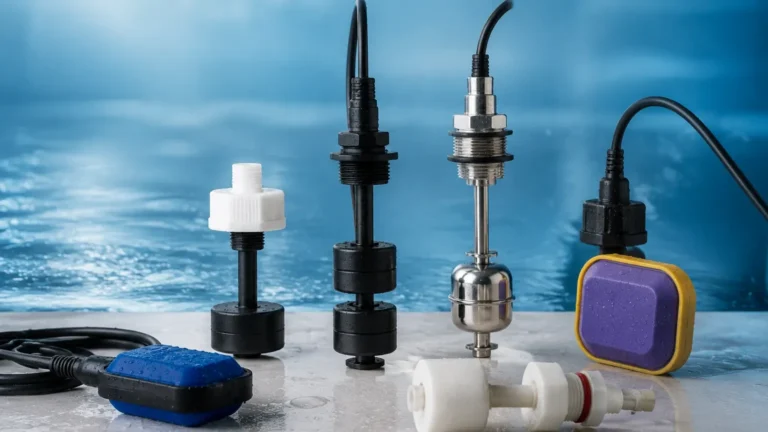
The most frequent implementation of a level 4 switch is the magnetic float design. This technology utilizes a hollow float containing a permanent magnet that slides up and down a stationary stem. Inside the stem, reed switches are positioned at precise intervals corresponding to the desired set points (e.g., 100 mm, 300 mm, 600 mm, and 900 mm).
As the liquid level rises or falls, the magnetic field from the float actuates the reed switches, opening or closing an electrical circuit. This method is highly reliable for clean liquids and does not require an external power source for the sensor element itself, making it an energy-efficient choice for remote or hazardous locations.
Conductivity Probes
Conductive level switches use the electrical conductivity of the liquid to complete a circuit. For a 4-level configuration, the assembly consists of five electrodes: one reference electrode (ground) and four detection electrodes cut to different lengths. When the conductive liquid touches an electrode, a small current flows between that electrode and the reference probe, signaling that the level has been reached.
This principle is restricted to conductive liquids (such as water, acids, or alkalis) and is often used in boiler water level control and wastewater treatment. It is valued for its lack of moving parts, which reduces mechanical wear.
Ultrasonic Point Sensors
Ultrasonic multi-point switches use the transmission of high-frequency sound waves across a gap in the sensor tip. When the gap is filled with air, the signal is attenuated; when the gap is submerged in liquid, the signal is transmitted efficiently to a receiver. For a level 4 switch setup, four separate ultrasonic sensor tips are integrated into a single probe. This technology is ideal for viscous liquids or applications where mechanical floats might become stuck due to debris or coating.
The Role of a Level 4 Switch in Process Control
A level 4 switch is typically configured to provide a comprehensive control logic for a vessel. The four points are usually assigned the following functions:
1. High-High (HH) Alarm: The uppermost point acts as an emergency stop or overfill protection. If the liquid reaches this level, the system may trigger an audible alarm and force-close inlet valves.
2. High (H) Level: This point often serves as the "Pump Stop" signal in a filling operation or a "Pump Start" signal in a drainage operation.
3. Low (L) Level: This point serves as the "Pump Start" signal for filling or the "Pump Stop" signal for drainage to ensure the tank does not empty completely during normal cycles.
4. Low-Low (LL) Alarm: The lowest point provides dry-run protection for pumps. If the level drops below this point, the system shuts down the pump to prevent cavitation and mechanical damage.
By using a single level 4 switch instead of four individual sensors, the facility benefits from a centralized signal output and a single entry point into the vessel, which is particularly advantageous for pressurized tanks where minimizing leak paths is a priority.
Technical Selection Criteria
Choosing the right level 4 switch requires an analysis of the chemical and physical properties of the media, as well as the operating environment. The following table summarizes the key factors for common multi-point technologies.
| Feature | Magnetic Float | Conductive Probes | Ultrasonic Multi-Point |
| :— | :— | :— | :— |
| Media Compatibility | Clean, non-coating liquids | Conductive liquids only | Viscous or aerated liquids |
| Max Temperature | Up to 180°C (356°F) | Up to 250°C (482°F) | Up to 135°C (275°F) |
| Max Pressure | Up to 40 bar (580 psi) | Up to 60 bar (870 psi) | Up to 20 bar (290 psi) |
| Moving Parts | Yes (Float) | No | No |
| Maintenance Requirement | Moderate (Cleaning) | Low | Low |
| Typical Applications | Fuel tanks, Oil sumps | Boilers, Water treatment | Chemical processing, Food & Bev |
Material Compatibility
The wetted parts of the switch must be chemically resistant to the process fluid. Common materials include Stainless Steel (304 or 316L) for general industrial use, and plastics like PVC, PP, or PVDF for corrosive acids and bases. For level 4 switches using magnetic floats, the float material must also be compatible with the liquid's specific gravity; if the float is too heavy, it will not rise with the liquid.

Installation and Configuration Guidelines
Proper installation is paramount to the longevity and accuracy of a level 4 switch. Consider the following engineering best practices:
* Avoid Turbulence: If the tank has an agitator or a high-velocity inlet, the movement of the liquid can cause the float to bounce or the electrodes to give false readings. In these cases, a stilling well (a vertical pipe with vent holes) should be installed around the switch to provide a calm environment for measurement.
* Vertical Alignment: Multi-point float switches must be installed vertically. A deviation of more than 15 degrees can increase friction between the float and the stem, leading to sticking.
* Wiring and Junction Boxes: Since a level 4 switch involves multiple circuits (often 8 wires for 4 SPST switches), ensure the junction box is appropriately rated (e.g., IP65 or IP67) for the environment. Use shielded cables if the switch signals are traveling long distances near high-voltage power lines to prevent electromagnetic interference.
* Dead Zones: Be aware of the "dead zones" at the very top and bottom of the probe. The floats cannot travel to the absolute ends of the stem due to the presence of mounting threads and end stops. Ensure your required set points fall within the active sensing range of the probe.
Limitations and Maintenance
While highly effective, level 4 switches have specific limitations that must be managed:
1. Build-up and Coating: In applications with wastewater or slurry, materials can accumulate on the float or the electrodes. For float switches, this may cause the float to seize. For conductive probes, a coating of non-conductive material can insulate the probe, preventing a signal. Regular inspection and cleaning cycles are necessary in these environments.
2. Specific Gravity Changes: Magnetic float switches are calibrated for a specific liquid density. If the process fluid changes (e.g., switching from oil to water), the float may sit higher or lower in the liquid, slightly shifting the switching points.
3. Mechanical Wear: Because reed switches have a finite number of cycles, they will eventually fail. It is recommended to use the level switch to trigger a high-impedance relay or PLC input rather than driving a high-current load (like a pump motor) directly, which would cause the reed contacts to weld together.
Frequently Asked Questions (FAQ)
Q: Can I adjust the set points of a level 4 switch after installation?
A: For most magnetic float switches, the reed switches are fixed inside the stem at the factory and cannot be moved. However, some modular designs allow for the user to slide the reed switch holders within the stem. Conductive probes can be adjusted by cutting the electrodes to a shorter length, but they cannot be made longer.
Q: What is the difference between N.O. (Normally Open) and N.C. (Normally Closed) in this context?
A: This refers to the state of the switch when the liquid is not present. Most level 4 switches can be configured as either. For safety-critical applications like high-level alarms, N.C. is often preferred so that a broken wire will trigger the same alarm state as a high liquid level (fail-safe).
Q: How do I handle foaming liquids?
A: Foam can cause false triggers in ultrasonic and conductive switches. If foam is a persistent issue, a magnetic float switch is generally the better choice, as the float will typically sink through the foam and only react to the actual liquid surface.
Q: Is a level 4 switch suitable for high-viscosity liquids?
A: High-viscosity liquids can impede the movement of a float. For these applications, non-contact methods or specialized tuning fork switches are recommended. If a float must be used, a larger float with higher buoyancy and a larger clearance between the float and stem should be specified.
By understanding these technical nuances, engineers can effectively implement a level 4 switch to provide robust, multi-point monitoring for complex industrial tanks. For more information on specific models and customized configurations, you can review product options and application support for various Level Switches to find the ideal solution for your process requirements.