Gauge Low
Gauge Low
In industrial process control, monitoring the minimum threshold of a liquid in a vessel is as critical as preventing an overflow. The term "gauge low" refers to the specific engineering challenge of ensuring that level measurement instruments accurately reflect the liquid state when it reaches the bottom of the measurable range. For operators and engineers, a "gauge low" condition is a critical point where pump cavitation, heater exposure, or process interruptions can occur.
Reliable monitoring at these lower limits requires a deep understanding of the mechanical and physical principles of Magnetic & Local Level Gauges. While modern automation often relies on remote sensors, local indicators remain the primary safety backup and verification tool for field personnel. This guide explores the principles, selection criteria, and installation nuances required to maintain accuracy during low-level conditions.
Measurement Principles of Local Level Gauges
Before addressing the complexities of low-level measurement, it is essential to understand how local level gauges function. Most mechanical level indicators operate on the principle of communicating vessels. This principle states that a liquid in a set of connected containers will settle at the same level in all containers, regardless of their shape or volume, provided the pressure remains constant.
Magnetic Level Gauges (MLG)
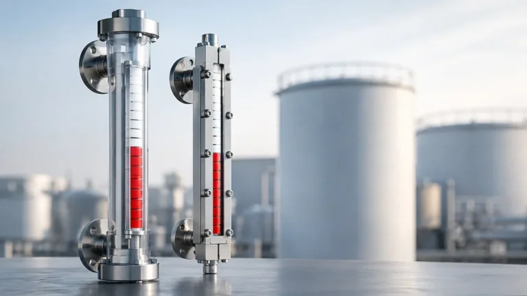
The Magnetic Level Gauge consists of a bypass chamber (a vertical pipe) attached to the side of a tank via two or more nozzles. Inside this chamber is a float containing a high-intensity omnidirectional magnet. As the liquid level in the tank rises or falls, the liquid in the chamber moves accordingly, carrying the float with it.
On the outside of the chamber, a sealed indicator rail contains bicolored flaps or a follower. The magnetic field from the float penetrates the chamber wall and interacts with the indicator. As the float passes, the flaps flip 180 degrees, changing color (typically from white to red) to provide a clear, high-visibility representation of the liquid level. Because the indicator is completely isolated from the process fluid, MLGs are ideal for high-pressure, toxic, or corrosive applications.
Glass Level Gauges
Traditional local gauges, such as reflex or transparent glass gauges, allow for direct visual inspection of the liquid. Reflex gauges use the principle of light refraction; the liquid-filled area appears dark, while the gas-filled area appears bright. Transparent gauges use two pieces of glass on opposite sides, allowing light to pass through the liquid, which is useful for observing interface levels or liquid color.
Understanding the "Gauge Low" Challenge
When a system is described as "gauge low," it implies that the liquid level is approaching the bottom limit of the instrument's sensing range. Several physical factors can interfere with accuracy at this stage.
The Bottom Dead Zone
Every magnetic level gauge has a "dead zone" at the top and bottom of the chamber. The bottom dead zone is the distance from the center of the bottom process connection to the point where the float begins to rise. Because the float has a specific length and weight, it requires a certain volume of liquid to become buoyant. If the liquid level is below the float's buoyancy point, the indicator will show a "low" reading that may not accurately reflect the actual remaining volume in the tank bottom. This is a primary concern in "gauge low" scenarios where every millimeter of fluid counts.
Specific Gravity and Buoyancy
The accuracy of a magnetic gauge at low levels is heavily dependent on the specific gravity (SG) of the liquid. A float designed for water (SG 1.0) will sit differently in a light hydrocarbon (SG 0.6). If the liquid density changes due to temperature fluctuations, the float may sit lower in the liquid, causing the gauge to report a lower level than what is actually present. Engineers must specify the minimum and operating SG to ensure the float is calibrated correctly for low-level detection.
Selection Criteria for Low-Level Applications
Choosing the right instrument to manage a gauge low condition involves evaluating the process environment and the physical properties of the media. The following table provides a comparison of common local level measurement technologies used in industrial settings.
Selection Table: Local Level Gauge Comparison
| Feature | Magnetic Level Gauge | Reflex Glass Gauge | Transparent Glass Gauge |
| :— | :— | :— | :— |
| Visibility | Excellent (up to 30m distance) | Good (requires proximity) | Moderate (requires backlighting) |
| Pressure Range | Up to 40 MPa (400 bar) | Up to 25 MPa (250 bar) | Up to 34 MPa (340 bar) |
| Temperature Range | -196°C to 450°C | Up to 400°C | Up to 400°C |
| Maintenance | Low (no glass to clean/break) | High (seals and glass cleaning) | High (frequent seal checks) |
| Low Level Accuracy | Dependent on float design | Direct visual (highly accurate) | Direct visual (highly accurate) |
| Corrosive Media | Excellent (PTFE/PVDF liners) | Limited by glass/gasket | Limited by glass/gasket |
Key Evaluation Factors
1. Chamber Material: For acidic or caustic environments, stainless steel (316L), Hastelloy, or plastic-lined chambers (PTFE) are required to prevent corrosion that could trap the float at the bottom.
2. Float Design: For low-density liquids, titanium floats are often used due to their high strength-to-weight ratio, allowing for a shorter float that reduces the bottom dead zone.
3. Redundancy: In critical "gauge low" applications, such as boiler drum level, it is common to use a magnetic level gauge equipped with a reed switch or a magnetostrictive transmitter to provide both local and remote low-level alarms.
Installation Considerations for Low-Level Accuracy
Proper installation is the most significant factor in ensuring that a "gauge low" reading is reliable. If the instrument is not positioned correctly relative to the tank's discharge point, the gauge may report that there is still liquid available when the pump has already run dry.
Nozzle Positioning
The bottom process connection (nozzle) should be placed as low as possible on the vessel side. However, if the tank has a high concentration of sediment or sludge, the nozzle should be placed slightly above the very bottom to prevent debris from entering the gauge chamber and pinning the float in the "low" position.
Zero-Point Calibration
The "zero" mark on the indicator scale must be aligned with the center of the bottom process connection or a specific datum point defined by the plant's engineering standards. In many cases, the "gauge low" point on the scale is actually 100 mm to 200 mm above the physical bottom of the chamber to account for the float's resting position.
Venting and Draining
To ensure the liquid in the chamber accurately follows the tank level, the chamber must be properly vented at the top and equipped with a drain valve at the bottom. During a "gauge low" condition, gas pockets trapped in the chamber can depress the liquid level, leading to a false low reading. Regular flushing through the drain valve prevents the accumulation of scale and solids that could interfere with float movement.

Limitations and Risks
While Magnetic & Local Level Gauges are robust, they are not without limitations in low-level scenarios:
* Coating and Scaling: If the process fluid is prone to crystallization or coating, the float may become heavy or stick to the chamber wall. This can result in a "frozen" reading where the gauge does not drop even as the tank reaches a low level.
* Magnetic Interference: External magnetic fields or nearby large ferrous structures can interfere with the coupling between the float and the indicator.
* High Turbulence: In tanks with heavy agitation, the liquid in the bypass chamber may surge. While the chamber acts as a natural stilling well, extreme turbulence can cause the float to bounce, making it difficult to discern a true gauge low state.
Maintenance and Troubleshooting for Low Levels
To prevent failures during critical low-level events, a preventative maintenance schedule should be implemented.
1. Float Inspection: Periodically remove the float to check for signs of collapse (due to over-pressure) or buildup of solids. A damaged float will not sit at the correct buoyancy level.
2. Indicator Verification: Use an external magnet to manually slide the indicator flaps to ensure they move freely. If flaps are stuck, they may fail to flip when the float descends to a low level.
3. Chamber Flushing: Use the drain connection to flush out any accumulated sludge. This is especially important in water treatment or oil-water separation applications where heavy phases settle at the bottom.
Frequently Asked Questions (FAQs)
Q: How do I know if my gauge is showing a false low?
A: Cross-reference the local gauge with a secondary instrument, such as a radar sensor or a pressure transmitter. If the MLG shows "low" but the secondary sensor shows a higher level, the float may be stuck or have lost its buoyancy.
Q: Can I use a magnetic level gauge for liquids with very low specific gravity?
A: Yes, but it requires a larger, specialized float to displace enough mass to remain buoyant. This often necessitates a larger chamber diameter (e.g., 3" or 4" pipe instead of the standard 2").
Q: What is the minimum liquid level a magnetic gauge can measure?
A: This depends on the "bottom dead zone" of the specific model. Typically, the measurement starts 100 mm to 250 mm above the bottom of the chamber. If you need to measure to the very bottom of the tank, a top-mounted level probe may be more appropriate.
Q: Why do the flags on my indicator stay red even when the level is low?
A: This usually indicates that the float is stuck at a higher position in the chamber or that the magnetic coupling has been broken by a rapid level change (surging). Resetting the flags with a handheld magnet and flushing the chamber usually resolves this.
Conclusion
Managing a "gauge low" condition effectively is a matter of precision engineering and regular maintenance. Whether using a magnetic level gauge for its safety and visibility or a glass gauge for direct inspection, understanding the physical limitations of the instrument is paramount. By considering factors like specific gravity, bottom dead zones, and proper nozzle placement, industrial facilities can ensure that their local indicators provide the reliable data needed to protect equipment and maintain process continuity. For high-stakes applications, always ensure that your selection aligns with the chemical and physical demands of your specific process media.