J Gauges
J Gauges
In the field of industrial process control, local level indication remains a critical safety and operational requirement. Among the various terminologies used by piping engineers and plant operators, "J gauges"—often referring to Jerguson-style or similar heavy-duty glass and magnetic level indicators—represent a standard for robust, direct-reading level measurement. These instruments provide a physical verification of tank levels that functions independently of electronic control systems, ensuring that operators have a reliable visual reference even during power failures or sensor malfunctions.
Selecting the correct Magnetic & Local Level Gauges requires an understanding of the mechanical principles governing fluid behavior, light refraction, and magnetic coupling. This guide explores the technical foundations of J-style local gauges, their application across various industries, and the engineering criteria necessary for safe integration into pressurized systems.
Measurement Principles of Local Level Gauges
Local level gauges operate on different physical principles depending on their construction. The three most common types found in industrial settings are reflex, transparent, and magnetic gauges.
Reflex Gauges
Reflex gauges utilize the principle of light refraction and reflection. The gauge glass features a series of prismatic grooves on the side facing the process fluid. When light enters the gauge, it reacts differently depending on whether it encounters gas or liquid:
* Gas/Vapor Phase: Light is reflected off the prisms back toward the observer, appearing as a bright silvery-white color.
* Liquid Phase: The liquid fills the prismatic grooves, changing the refractive index and allowing light to pass through into the fluid. This results in the liquid column appearing dark or black.
This high-contrast display makes reflex gauges ideal for clean, colorless liquids where a clear interface is required.
Transparent Gauges
Transparent gauges consist of two pieces of flat glass sandwiching the liquid chamber. This allows light to pass entirely through the instrument. These are used primarily in two scenarios:
1. Interface Measurement: Observing the boundary between two immiscible liquids (e.g., oil and water).
2. Dirty or Corrosive Fluids: When the fluid might coat the prisms of a reflex gauge, a transparent gauge with protective shields (such as mica or PCTFE) is used to prevent glass erosion while maintaining visibility.
Magnetic Level Gauges
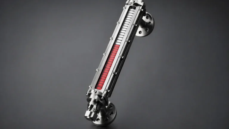
Magnetic gauges, often grouped under the broader category of J gauges in modern specifications, eliminate the risks associated with glass breakage. They operate via a float containing an internal magnet assembly. As the float rises and falls with the liquid level in a bypass chamber, its magnetic field couples with an external indicator—typically a series of bi-color magnetic flags or a follower. This "sealless" design ensures that the process fluid is entirely contained within a metal pressure housing.
Technical Selection Criteria
Choosing between different local level indicators involves balancing pressure ratings, chemical compatibility, and visibility requirements. The following table provides a general comparison of the primary technologies used in industrial J gauges.
Selection Table: Local Level Gauge Comparison
| Feature | Reflex Glass Gauges | Transparent Glass Gauges | Magnetic Level Gauges |
| :— | :— | :— | :— |
| Max Pressure | Up to 25 MPa (3625 PSI) | Up to 20 MPa (2900 PSI) | Up to 42 MPa (6000+ PSI) |
| Max Temp | 400°C (752°F) | 380°C (716°F) | 450°C (842°F)+ |
| Visibility | High contrast (B/W) | Moderate (requires light) | Excellent (colored flags) |
| Interface | Not Recommended | Excellent | Possible with weighted float |
| Hazardous Fluids | Limited (glass risk) | Limited (glass risk) | Highly Recommended |
| Maintenance | Moderate (gaskets/glass) | Moderate (cleaning/shields) | Low (no glass cleaning) |
Engineering Considerations for J Gauges
When specifying J gauges for a project, several engineering factors must be confirmed to ensure the longevity of the instrument and the safety of the facility.
Material Compatibility
The wetted parts—typically the gauge body, gaskets, and valves—must be compatible with the process media. Standard bodies are often constructed from Carbon Steel, Stainless Steel 304/316L, or specialized alloys like Monel or Hastelloy for highly corrosive environments. Gasket selection is equally vital; Graphite or PTFE-based gaskets are common, but high-pressure steam applications may require specialized metallic-reinforced gaskets.
Steam Applications and Glass Protection
In high-pressure steam boilers, the alkalinity of the water can rapidly erode borosilicate glass. For these applications, transparent gauges must be fitted with mica shields. The mica acts as a sacrificial barrier, preventing the steam and water from coming into direct contact with the glass surface, thereby extending the service life of the J gauge significantly.
Center-to-Center Dimensions
Local gauges are usually mounted to the side of a vessel via nozzles. The "Center-to-Center" (C-C) distance is the measurement between the midpoints of these nozzles. Because glass gauges have limited individual lengths (typically up to 300 mm or 12 inches per section), longer ranges are achieved by stacking multiple glass sections in a staggered or continuous configuration. Magnetic gauges, by contrast, can be manufactured in single continuous lengths exceeding 6 meters (20 feet).
Installation and Commissioning Best Practices
Proper installation is paramount to prevent leaks and ensure accurate readings. Following these guidelines will help maintain the integrity of the Magnetic & Local Level Gauges installation:
1. Alignment: Ensure that the vessel nozzles are perfectly aligned. Forcing a rigid metal gauge body to fit misaligned nozzles can introduce mechanical stress, leading to glass breakage or gasket failure under thermal expansion.
2. Support Brackets: For gauges exceeding 1.5 meters (5 feet) in length, external support brackets should be used to prevent vibration and stress on the process connections.
3. Isolation and Venting: Every J gauge should be installed with isolation valves (offset valves are preferred for glass gauges to allow for cleaning rods) and a drain/vent configuration. This allows the gauge to be safely depressurized and drained for maintenance without shutting down the entire process.
4. Thermal Expansion: In high-temperature applications, the gauge body will expand at a different rate than the vessel. Expansion loops or sliding mounts may be necessary to prevent structural damage.
Limitations and Operational Risks
While J gauges are highly reliable, they are not without limitations. Engineers should be aware of the following risks:
* Glass Fragility: In glass-based J gauges, mechanical impact or rapid thermal shock (introducing cold liquid into a hot gauge) can cause the glass to shatter. This is a significant risk when handling toxic or flammable fluids.
* Fouling and Coating: If the process fluid is highly viscous or prone to crystallization, it can coat the interior of the glass or the float in a magnetic gauge. This leads to "frozen" readings where the indicated level does not reflect the actual tank level.
* High-Pressure Limitations: As pressure increases, the thickness of the glass required for safety increases, which can eventually reduce visibility and increase the weight of the instrument to impractical levels. In these cases, magnetic level gauges are the preferred engineering solution.
Maintenance Requirements
Routine inspection of J gauges should include checking for signs of gasket weeping, glass thinning (in steam service), and the clarity of the viewing area. For magnetic gauges, maintenance is generally lower, but it is recommended to periodically flush the chamber to remove sediment that could interfere with float movement.
If a glass gauge requires disassembly, it is critical to follow a specific bolt-tightening sequence and torque specification. Uneven torquing is the leading cause of glass breakage during commissioning. Always replace gaskets whenever a gauge is opened; reusing old gaskets often leads to leaks once the system is pressurized.
Frequently Asked Questions (FAQs)
Q: Can reflex J gauges be used for liquid-liquid interface measurement?
A: No. Reflex gauges rely on the refractive index difference between gas and liquid. The contrast between two liquids (like oil and water) is usually insufficient to be seen clearly in a reflex gauge. A transparent gauge or a magnetic gauge with a specifically weighted float should be used instead.
Q: What is the maximum temperature for a standard J-style glass gauge?
A: Standard borosilicate glass is typically rated up to 280°C (536°F). With the addition of mica shields and specialized aluminosilicate glass, ratings can be extended to approximately 380°C to 400°C. For temperatures exceeding this, magnetic gauges are generally required.
Q: Why is my magnetic gauge showing a different level than my radar transmitter?
A: This is often due to density variations. Local gauges (both glass and magnetic) are sensitive to the actual density of the fluid in the bypass chamber. If the fluid in the chamber is cooler than the fluid in the tank, its density will be higher, resulting in a lower indicated level compared to a non-contact radar transmitter that measures the physical top of the liquid.
Q: How do I prevent "clouding" of the gauge glass?
A: Clouding is usually caused by chemical attack or mineral deposits. For chemical attack, upgrade the glass type or add a protective shield (Mica or PCTFE). For mineral deposits, regular flushing via the drain valve is necessary to prevent buildup.
Conclusion
Whether utilizing traditional glass-based reflex designs or modern magnetic coupling, J gauges remain an indispensable component of industrial level instrumentation. By providing a direct, mechanical link to the process, they offer a final layer of verification that electronic sensors cannot replace. When selecting these instruments, prioritizing material integrity, pressure safety, and clear visibility ensures that the Magnetic & Local Level Gauges will provide years of reliable service in even the most demanding process environments.