Jl Gauges
Jl Gauges
In industrial process control, the ability to monitor liquid levels locally—directly at the tank or vessel—remains a critical safety and operational requirement. Among the various technologies used for this purpose, jl gauges, a common designation for specific configurations of magnetic level indicators, have become a standard in many chemical, water treatment, and oil and gas facilities. These devices provide a clear, high-visibility visual representation of liquid levels without the risks associated with traditional glass sight gauges.
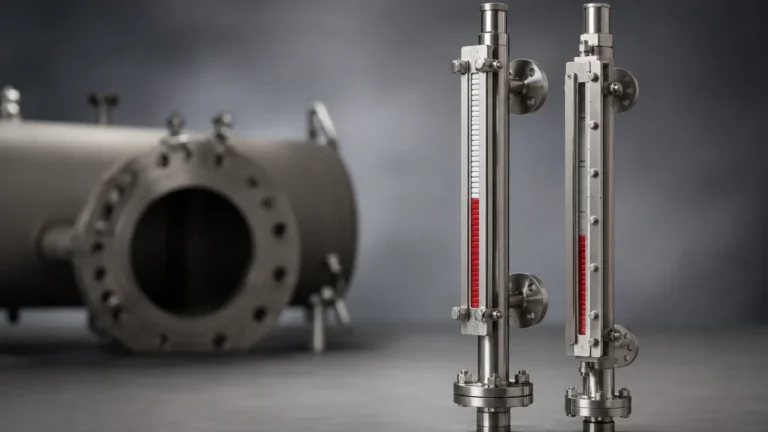
Magnetic & Local Level Gauges serve as the primary interface for operators on the plant floor. By utilizing magnetic coupling rather than direct contact between the process fluid and the viewing window, these instruments offer a robust solution for high-pressure, high-temperature, or corrosive environments. Understanding the engineering principles, selection criteria, and installation requirements of these gauges is essential for ensuring long-term reliability and site safety.
Measurement Principles of Magnetic Level Gauges
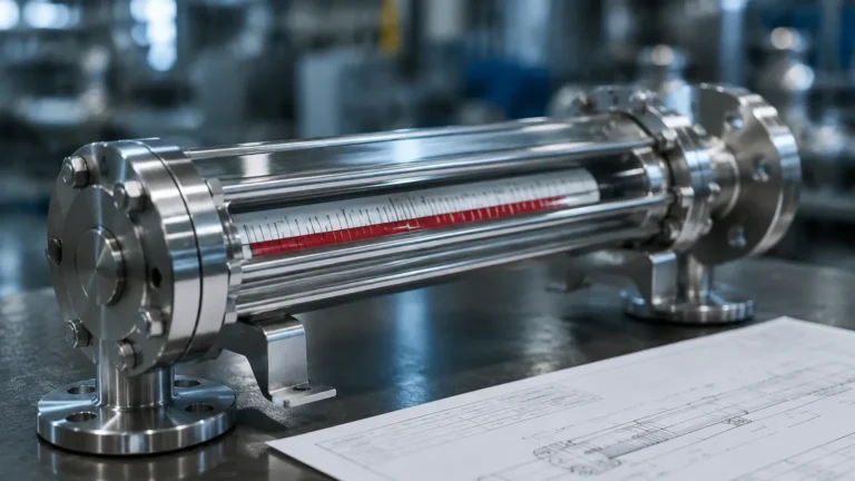
The operation of jl gauges and similar magnetic indicators is based on two fundamental physical principles: buoyancy and magnetic coupling. Unlike a standard sight glass where the fluid is visible through a transparent tube, a magnetic gauge uses a sealed chamber and an internal float.
The Buoyancy Principle
Inside the bypass chamber (a vertical pipe connected to the vessel), a float is designed to have a density lower than the process liquid. According to Archimedes' principle, the float will remain partially submerged and rise or fall as the liquid level changes. The engineering of the float is the most critical aspect of the gauge; it must be weighted precisely to match the specific gravity (SG) of the liquid while remaining strong enough to withstand the operating pressure of the vessel.
Magnetic Coupling
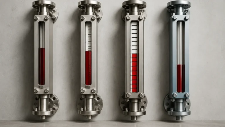
Contained within the float is a high-intensity permanent magnet (typically 360-degree magnetic ring). Outside the sealed chamber, a visual indicator—often referred to as a scale or display rail—is mounted. This indicator contains a series of bi-color magnetic flags or rollers (usually red and white or yellow and black). As the float moves vertically with the liquid level, its internal magnet interacts with the magnetic flags, flipping them 180 degrees. This change in color provides a distinct, high-contrast visual representation of the level that can be read from a significant distance.
Comparison of Local Level Measurement Technologies
When selecting a local level indicator, engineers must choose between different technologies based on the application's severity. The following table compares the most common types of local level gauges.
| Feature | Magnetic Level Gauges (JL Style) | Reflex Glass Gauges | Transparent Glass Gauges |
| :— | :— | :— | :— |
| Visibility | Excellent (High contrast flags) | Good (Dark/Light contrast) | Moderate (Requires light) |
| Pressure Rating | Up to 320 bar (Custom) | Up to 250 bar | Up to 120 bar |
| Temperature Range | -196°C to +450°C | -10°C to +400°C | -10°C to +380°C |
| Corrosive Resistance | High (Exotic materials/linings) | Moderate (Glass etching) | Moderate (Glass etching) |
| Risk of Leakage | Very Low (Sealed chamber) | Moderate (Gasket/Glass failure) | Moderate (Gasket/Glass failure) |
| Remote Output | Easily integrated (Transmitters) | Difficult/Not standard | Difficult/Not standard |
Key Components of Jl Gauges
A standard jl gauge assembly consists of several engineered components that must work in unison to provide accurate readings.
1. Bypass Chamber: This is the pressure-containing vessel, usually constructed from 304 or 316L stainless steel, though specialized plastics like PVC or PP are used for low-pressure corrosive applications. It is connected to the tank via side-side, top-bottom, or side-bottom configurations.
2. Magnetic Float: The float is the "heart" of the gauge. It is often constructed from thin-walled titanium or stainless steel to ensure it is light enough to float in low-density liquids (as low as 0.45 SG) while maintaining structural integrity under pressure.
3. Indicator Rail: This is the external assembly containing the magnetic flags. It is typically housed in a rugged, weather-proof enclosure (IP65 or higher) to prevent dust and moisture from interfering with the flag rotation.
4. Process Connections: These are the flanges or threaded NPT/BSP connections that attach the gauge to the vessel. They must match the pressure rating of the tank.
5. Vent and Drain: Standard on most jl gauges, these allow for the chamber to be emptied for maintenance or vented during startup to prevent air pockets from affecting the reading.
Material Selection and Chemical Compatibility
The longevity of Magnetic & Local Level Gauges depends heavily on material compatibility. Since the bypass chamber and float are in constant contact with the process media, the following material considerations are standard in B2B procurement:
* Stainless Steel (316/316L): The default for water treatment and general chemical applications due to its balance of strength and corrosion resistance.
* PTFE/PFA Lining: For highly aggressive acids (such as sulfuric or hydrochloric acid), the interior of the stainless steel chamber can be lined with fluoropolymers. In these cases, the float is also typically made of or coated with a compatible plastic.
* Titanium: Used for high-temperature, high-pressure applications where weight is a factor, or in seawater environments where stainless steel may suffer from pitting.
* Hastelloy/Inconel: Reserved for extreme chemical environments where standard alloys fail.

Installation Considerations for Engineers
Proper installation is paramount for the accuracy of jl gauges. Unlike electronic sensors that can often be calibrated to account for mounting errors, a mechanical magnetic gauge relies on physical alignment.
Vertical Alignment
The bypass chamber must be installed perfectly vertical. Even a slight tilt can cause the float to rub against the chamber walls, leading to friction that prevents the float from moving smoothly or causes it to get stuck. A deviation of more than 3 degrees is generally considered unacceptable.
Magnetic Interference
Because the device operates on magnetic coupling, it must be kept away from large ferrous structures or high-voltage power lines that could create electromagnetic fields. If the gauge is installed too close to a steel support beam, the magnet in the float may be attracted to the beam rather than the indicator flags.
The "Dead Band"
Every magnetic level gauge has a "dead band" at the top and bottom of the chamber. This is the space required for the float to rest without blocking the process connections. When designing a tank, engineers must ensure the desired measurement range falls between these two dead bands. If the tank level drops below the bottom process connection, the float will sit on the bottom spring, and the gauge will show a constant "empty" reading even if the tank is not completely dry.
Limitations and Operational Risks
While jl gauges are highly reliable, they are not suitable for every application. Engineers should be aware of the following limitations:
* Particulate Matter: If the process liquid contains magnetic particles (such as iron filings or scale), these particles will adhere to the magnetic float. Over time, this buildup increases the float's weight and can eventually cause it to sink or become jammed in the chamber.
* High Viscosity: Extremely viscous liquids can slow the movement of the float, leading to a lag between the actual liquid level and the displayed level. In some cases, the liquid may coat the float, changing its buoyancy.
* Flash Vaporization: In high-temperature applications, if the pressure in the chamber drops rapidly, the liquid may "flash" into vapor. This turbulence can damage the float or cause it to bounce violently, leading to inaccurate readings.
Maintenance and Troubleshooting
Magnetic gauges are generally low-maintenance because they have no moving parts exposed to the external environment. However, a routine inspection schedule should include:
1. Chamber Flushing: Periodically opening the drain valve to flush out any sediment or sludge that has settled at the bottom of the chamber.
2. Float Inspection: If the gauge reading becomes sluggish, the float should be removed and inspected for pinhole leaks or coating buildup.
3. Flag Alignment: Occasionally, external vibrations or nearby magnetic activity can flip a flag out of sequence. Most gauges can be "reset" by sliding a handheld magnet up the outside of the indicator rail to realign all flags to the current level.
Frequently Asked Questions (FAQ)
Q: Can jl gauges be used for interface measurement (e.g., oil and water)?
A: Yes. By specifically weighting the float to a density between the two liquids (e.g., 0.85 SG), the float will sink through the upper layer and float on the lower layer, indicating the interface level.
Q: What is the maximum distance for visual reading?
A: Depending on the size of the flags, most magnetic level gauges are easily readable from 20 to 30 meters. For even greater visibility, wide-flag versions or illuminated scales are available.
Q: How do I add a remote signal to a manual jl gauge?
A: You can strap a reed-switch transmitter or a magnetostrictive sensor to the outside of the chamber. These sensors detect the position of the float's magnet and convert it into a 4-20mA or HART signal without needing to penetrate the pressure boundary.
Q: Are these gauges suitable for sanitary food and beverage applications?
A: Yes, provided they are manufactured with polished stainless steel surfaces and tri-clamp connections to meet 3A or EHEDG standards.
By adhering to these technical guidelines and understanding the specific requirements of the process media, jl gauges provide a dependable, "set-and-forget" solution for local level monitoring. For complex applications involving high pressures or aggressive chemicals, consulting with a specialist in Magnetic & Local Level Gauges ensures that the instrument's materials and float design are perfectly matched to the operational environment.