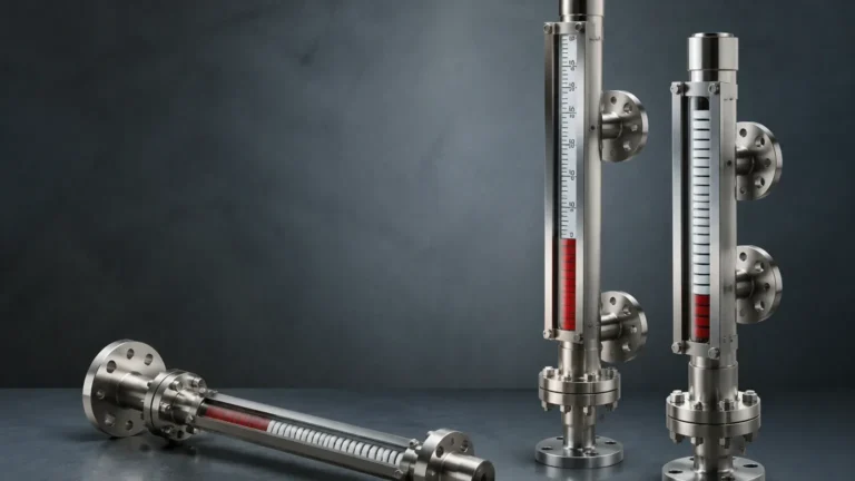
M Gauge
M Gauge
In the landscape of industrial process control, the term "m gauge" is frequently employed by field engineers and procurement specialists as a shorthand for the Magnetic Level Gauge. These instruments serve as a critical interface between the physical state of a liquid within a vessel and the monitoring requirements of the operator. As a primary method for local level indication, the magnetic gauge offers a robust, power-free visual reference that remains reliable even in the event of a total plant power failure.
For facilities managed by Welk and similar industrial entities, selecting the correct Magnetic & Local Level Gauges involves a deep understanding of fluid dynamics, material compatibility, and magnetic coupling principles. This guide provides a comprehensive technical overview of the m gauge, covering its operational mechanics, selection criteria, and installation best practices for water treatment, chemical processing, and oil and gas applications.
Measurement Principles of the Magnetic Level Gauge
The operation of an m gauge is based on two fundamental physical principles: the law of communicating vessels and the principle of magnetic coupling. Unlike traditional glass sight gauges, which rely on the transparency of the fluid and the integrity of a glass tube, the magnetic gauge utilizes a metallic bypass chamber and a specialized internal float.
Communicating Vessels
Because the gauge is connected to the side of a tank or vessel via process flanges, the liquid level inside the gauge chamber equalizes with the level inside the tank. This ensures that any change in the tank's liquid level is instantaneously reflected within the chamber.
Magnetic Coupling
Inside the chamber is a float specifically engineered to match the specific gravity (density) of the process medium. This float contains a high-intensity permanent magnet assembly. As the float rises or falls with the liquid level, its magnetic field penetrates the non-magnetic wall of the chamber (usually stainless steel or a specialized alloy).
On the exterior of the chamber, an indicator rail is mounted. This rail contains a series of magnetic flaps or rollers, often painted with contrasting colors (typically red for the liquid phase and white for the vapor phase). As the float passes, the magnetic force flips the flaps 180 degrees, creating a clear, high-contrast visual representation of the liquid level. Because this coupling is purely magnetic, there is no physical connection between the process fluid and the indicator, significantly reducing the risk of leaks.
Key Components and Construction
An industrial-grade m gauge consists of several critical components, each of which must be specified based on the application's environmental and chemical demands.
1. The Chamber: This is the primary pressure boundary. It is typically constructed from 304 or 316L Stainless Steel, though exotic materials like Hastelloy, Titanium, or PVC/CPVC are used for highly corrosive environments. The chamber diameter is usually 2 inches (approx. 50mm) to 3 inches (approx. 75mm) to allow sufficient clearance for the float.
2. The Float: The float is the most sensitive component. It must be light enough to float on the liquid but strong enough to withstand the operating pressure. For high-pressure applications, floats are often pressurized or made from high-strength titanium. The magnetic ring inside the float is positioned precisely at the fluid's buoyancy line.
3. The Indicator Rail: This is the visual component. In addition to mechanical flaps, some modern indicators include a graduated scale in millimeters, meters, or percentage. For low-light environments, LED-backed indicators are available.
4. Process Connections: These are the flanges or threaded NPT/BSP connections that attach the m gauge to the vessel. Their rating (e.g., ANSI 150#, PN16) must match or exceed the vessel's design pressure.
Practical Selection Criteria for M Gauges
Selecting an m gauge requires precise data regarding the process fluid. A mismatch in specifications can lead to float failure (sinking) or chamber rupture. Engineers should use the following table as a baseline for preliminary selection.
Selection Matrix for Magnetic Level Gauges
| Parameter | Specification Range (Standard) | High-Performance Options |
| :— | :— | :— |
| Operating Pressure | Vacuum to 4.0 MPa (40 bar) | Up to 20.0 MPa (200 bar) |
| Operating Temperature | -20°C to 150°C | -196°C (Cryogenic) to 450°C |
| Fluid Density (SG) | 0.80 to 1.20 g/cm³ | Min. 0.45 g/cm³ (Interface) |
| Viscosity | < 100 cP | Up to 500 cP (with oversized chamber) |
| Measuring Range | 300 mm to 6,000 mm | Up to 15,000 mm (Sectional design) |
| Material | SS304 / SS316L | PTFE Lined, Hastelloy, PVC, PP |
When specifying an m gauge, the Specific Gravity (SG) is the most critical variable. If the actual fluid density is lower than the float's design density, the float will sink to the bottom of the chamber, resulting in a false "empty" reading. Conversely, if the density is higher, the float will sit too high, leading to an offset in the visual accuracy.
Installation Considerations and Best Practices
Proper installation is paramount to ensuring the longevity and accuracy of the m gauge. Because these instruments rely on mechanical movement and magnetic fields, certain environmental factors must be managed.
Vertical Alignment
The chamber must be installed perfectly vertical. Even a slight tilt (greater than 2-3 degrees) can cause the internal float to rub against the chamber walls, leading to friction that prevents smooth movement or causes the float to stick entirely.
Magnetic Interference
Since the device operates via magnetic coupling, it must be kept away from large ferrous structures or high-voltage electrical lines that could generate electromagnetic fields. A minimum clearance of 100mm to 200mm from steel supports is generally recommended to prevent "magnetic drag" on the internal float.
Bypass Piping and Valves
It is standard engineering practice to install isolation valves (ball or gate valves) between the vessel and the m gauge. This allows the gauge to be serviced or cleaned without depressurizing the main tank. Additionally, a drain valve at the bottom and a vent valve at the top of the gauge chamber are essential for commissioning and removing sediment.
Insulation and Heat Tracing
In applications involving high-viscosity liquids (like heavy crude or resins) or fluids that crystallize at ambient temperatures, the m gauge chamber should be heat-traced or insulated. However, the insulation must not interfere with the visibility of the indicator rail.

Limitations and Environmental Risks
While the m gauge is a versatile tool, it is not suitable for every application. Understanding its limitations prevents costly measurement errors.
* Ferrous Particles: If the process fluid contains iron filings or magnetic scale, these particles will adhere to the internal float's magnets. Over time, this buildup will increase the float's weight and eventually jam it against the chamber wall. Magnetic filters (traps) can be installed in the process lines to mitigate this, but they require regular maintenance.
* High Viscosity and Coating: Extremely viscous fluids can create a coating on the chamber wall or the float, increasing friction. If the fluid "gums up," the float may become trapped, providing a static reading while the actual tank level changes.
* Flash Vaporization: In boiling liquids, rapid gas evolution can cause the float to bounce violently. This "chatter" can damage the internal magnets or the indicator flaps. In such cases, a damping spring or a larger chamber diameter may be required.
Integration with Automation Systems
Modern m gauge installations often serve a dual purpose: local visual indication and remote electronic monitoring. This is achieved by adding accessories to the external chamber without breaching the pressure boundary.
* Reed Switch Transmitters: A series of reed switches mounted in a tube alongside the chamber can provide a 4-20mA signal proportional to the level. This allows the m gauge to communicate with a PLC or DCS.
* Magnetic Switches: Point-level switches can be clamped to the chamber at specific heights (e.g., High-High or Low-Low) to trigger alarms or emergency shutdowns. These switches are actuated by the float's magnetic field as it passes.
* Magnetostrictive Sensors: For high-precision requirements, a magnetostrictive probe can be mounted to the m gauge. This provides accuracy levels of +/- 1mm, combining the reliability of a visual gauge with the precision of advanced electronics.
Frequently Asked Questions (FAQs)
Q: How often should an m gauge be calibrated?
A: Mechanically, an m gauge does not require calibration in the traditional sense because its operation is based on physical buoyancy. However, the external 4-20mA transmitters or switches should be verified annually. The chamber should also be flushed periodically to remove sediment.
Q: Can an m gauge be used for interface measurement (e.g., oil and water)?
A: Yes. By designing a float with a density that falls between the densities of the two liquids (e.g., 0.85 g/cm³), the float will sink through the upper layer and float on the lower layer, effectively indicating the interface level.
Q: What happens if the float is installed upside down?
A: Most floats are directional because the magnet assembly is weighted to sit at the fluid's surface. Installing a float upside down will usually result in an inaccurate reading or a failure of the indicator to flip the flaps correctly. Most manufacturers mark the "Top" of the float clearly.
Q: Is it possible to repair a collapsed float?
A: No. If a float collapses due to a pressure surge exceeding its design rating, it must be replaced. It is critical to ensure that the design pressure of the float exceeds the maximum possible surge pressure of the system.
Conclusion
The m gauge remains a cornerstone of industrial level measurement due to its simplicity and the safety provided by its clear visual indication. By eliminating the risks associated with glass breakage and providing a reliable secondary measurement that functions without power, it ensures that operators always have eyes on the process. When specified correctly—taking into account fluid density, pressure, and chemical compatibility—the Magnetic & Local Level Gauges provided by Welk offer a long-term, low-maintenance solution for the most demanding industrial environments. Proper attention to installation and the management of magnetic interference will ensure these instruments provide accurate data for years of service.